Electricity
Electrical Technician
MINDS ON
Electricians Communicate with Circuit Symbols
Imagine that one day you are working as an electrician (definition:A person who installs, operates, maintains, or repairs electrical devices or electrical wiring) and the boss asks you to build a circuit that wires a room, with the following requirements:
“The breaker panel should be arranged in six parallel branches: three of them containing two outlets and six lights, two of them with four outlets and two lights, and one of them as a separate line that connects to one of the outlets in the 4-2 branch. And make it fast!” (Wood, 2017)
In addition, your boss may give you a diagram to support their request above:
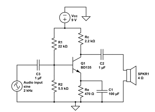
uses symbols to communicate how
each component is connected.
by Unknown author used under ShareAlike CC BY-SA
It may feel like what your boss has asked for verbally and what has been shown in the above diagram could be a different language altogether! As you can see, electricians communicate using a set of symbols that form a schematic circuit diagram to show how the electrical components are connected.
Each electrical component in a circuit has its own symbol to represent it. Review the image below (and click here to load a PDF document) to learn common electric circuit symbols.

 Save your work and add to your Electricity Mind Map
- The image above showing common Circuit Symbols, is a good tool to use when constructing circuit diagrams and decoding information.
- SAVE this document in such a way that you can make reference to it later.
- When saving documents ensure you have named the file with a meaningful title so you can refer back to it easily.
- Example - for the Graphic Organizer:
- U3A3_CircuitSymbols_LastName.doc
- To further develop your skills of responsibility, it would be a good time to add information to your Electricity Mind Map.
Drawing Electric Circuits
U3A3Circuits
ACTION
Building an Electrical Circuit
 Designing and Building Electrical Circuits
TASK #1 - Designing a Circuit
- Design a circuit by creating a schematic diagram (definition:diagram using circuit symbols) that shows a circuit that can do the following things:
- Have three lights that can light up individually.
- All lights can be turned off at the same time.
- Light Bulb #1 and Light Bulb #2 WILL light up, but Light Bulb #3 DOES NOT.
- Light Bulb #1 and Light Bulb #3 WILL light up, but Light Bulb #2 DOES NOT.
- Three batteries connected in series.
- The schematic diagram can be completed using a digital drawing software OR handwritten.
- Take a picture of your design (if handwritten) and/or SAVE (if digital) the diagram.
Tip: Save Your Work
- When you have completed your schematic diagram (handwritten OR digital), SAVE this document in such a way that you can make reference to it later.
- When saving documents ensure you have named the file with a meaningful title so you can refer back to it easily.
Designing and Building Electrical Circuits (continued)
TASK #2 - Build a Circuit
Build the circuit you have designed (from Task #1) by using the PhET Circuit Builder Simulation.
- When you have tested that your circuit meets the functional criteria from Task #1, create a video explanation using Screencastify where you can demonstrate how your circuit works while narrating as you work on the computer screen.
- When you create your circuit and video explanation consider including the following discussion points:
- Does the circuit design satisfy the functions from outlined in Task #1?
- What type of circuit (series or parallel) have you created and how do you know?
- Does your built circuit reflect your original design?
- Did you need to make any change or alterations?
- Why is it important to design using a schematic circuit diagram prior to building?
- When you create your circuit and video explanation consider including the following discussion points:
Exploring Series and Parallel Circuits
Note: This activity is optimized for a tablet or larger screen size. Be sure to view the interactive in fullscreen mode. Also on tab #1 of the interactive scroll down to the bottom of the screen to locate the Phet Circuit Builder Simulation or open the PhET Circuit Builder Simulation in a new window and toggle back and forth between the activity and the lab. Important: The next button in the interactive is disabled until all of the 9 simulations have been completed. Sorry there is no shortcut for this activity ;-)
U3A3SeriesParallelCircuits
Tip: Save Your Work
- When you have completed the circuit building interactive click print to compile your work.
- SAVE this document in such a way that you can make reference to it later.
- When saving documents ensure you have named the file with a meaningful title so you can refer back to it easily
CONSOLIDATION
Summarizing our Knowledge...Wire a Wall!
In the previous activity, you learned how to be safe with electricity and the difference between voltage, current and resistance. In this activity you have learned how current electricity can flow in different circuit types; how a circuit behaves, depending on its series or parallel nature; and how to communicate a diagram of the circuit.
Wiring a Wall
Imagine you have been hired as an electrical apprentice and asked to summarize and demonstrate your knowledge, by designing the electrical wiring of a living room. Your living room circuit should consist of a minimum of the following electrical components:
- One power supply
- One switch that controls the current through a light
- One electrical outlet that is NOT controlled by the switch (if the light goes ‘on and off’ with the switch, the electrical outlet is still powered.
- One light bulb (lamp)
Your circuit diagram submission that includes the following:
- Clear circuit symbols showing proper electron pathways
- A clear explanation (written or verbal recording) about the circuit that discusses:
- What type of circuit is being used (series or parallel) and why?
- What considerations were made about the safety of wiring and voltage?
- What materials would be used to consider optimal conduction (definition:material that allows the flow of electrons), insulation (definition:material that impedes the flow of electrons) and resistance (definition:speed of electron flow can be influenced by temperature, thickness, length and material type of the wire.) properties of the wires?