Simple Machines
Torque, Levers, and Mechanical Advantage
MINDS ON

 Reflection
Create a reflection to answer the following questions:
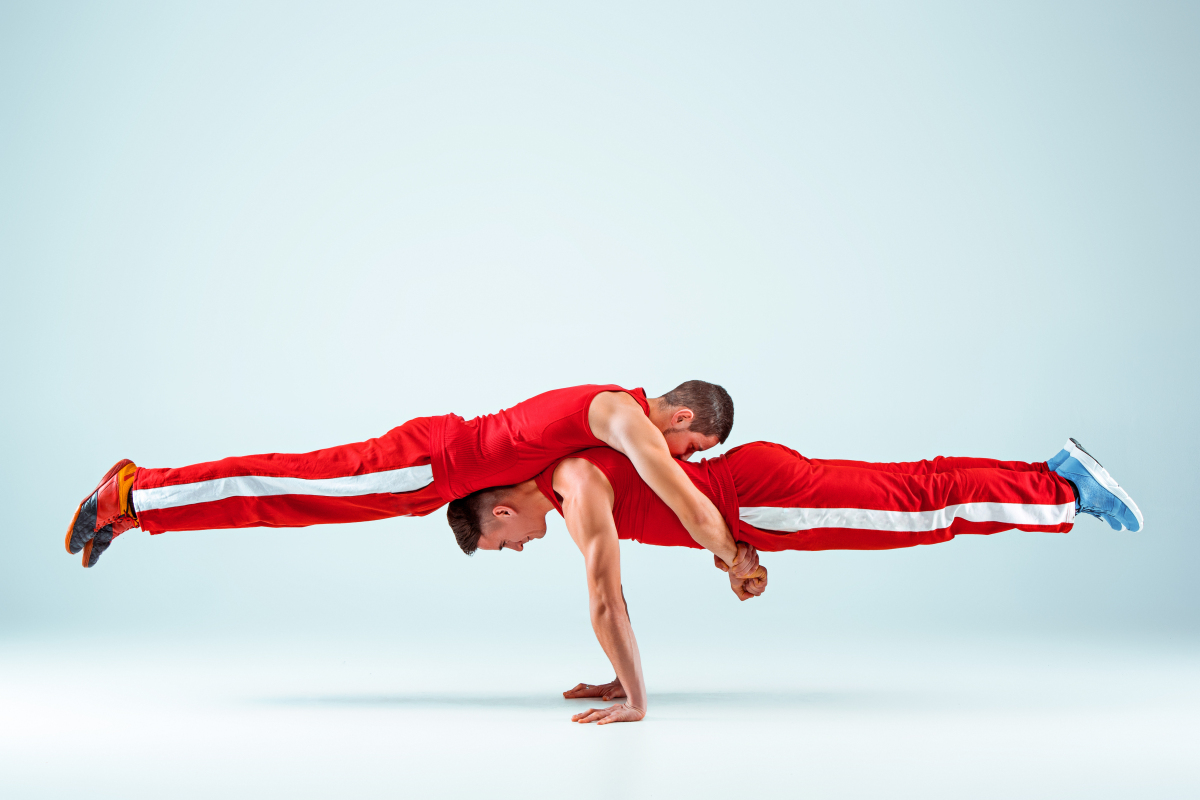
- What similarities and differences do you notice about these two pictures?
- What would cause both of them to collapse? Explain your reasoning
ACTION
There are two main families of simple machines – the lever family and the inclined plane family. Just like most families share similar physical or behavioural characteristics, so too do the members of each simple machine family.
We will learn to identify and analyze each family member through a physics lens and learn how each makes our lives easier on a daily basis.
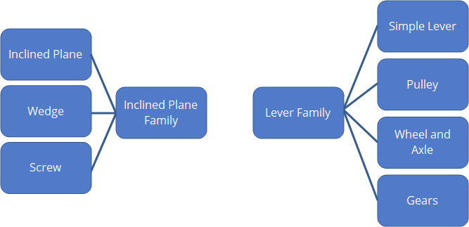
Let’s start with the lever family!
Lever Family
Did you know that you use levers every day? Our entire biomechanical system is made up of many different levers that work together so that we can move heavy objects, bite into our food, and throw a baseball.
A lever is a simple machine used to change the magnitude and the direction of forces. A lever is a rigid body or beam that rotates on a central axis called a fulcrum. An input force called the effort force,  , is applied to the rigid body a distance,
  (effort arm) from the fulcrum to move an often much larger output force called the load force,
  located a distance
  (load arm) from the fulcrum. The effort arm and the load arm are always measured as the distance from the effort force and load force to the fulcrum respectively.
Levers can be classified into three different classes based on the locations of the effort and load forces in reference to the fulcrum.
First-Class Lever
A first-class lever is a lever with the effort force and the load force located on opposite sides of the fulcrum. These levers are exceptional at requiring a small effort force to move a very large load force.

The beaker depicted in the photo above is providing the load force. This force is the weight of the object and is directed down. The beaker is causing the rigid balance beam to rotate counter-clockwise around the fulcrum. The counter weights used to balance the beaker are providing the effort force. This force is directed down as well, but in this case the counter weights are causing the rigid balance beam to rotate clockwise around the fulcrum.
Second-Class Lever
A second-class lever is a lever with the effort force and the fulcrum located on opposite sides of the load force. These levers are known to require much less effort force to move a large load force. The distance the effort force moves is much larger than the distance the load force moves.
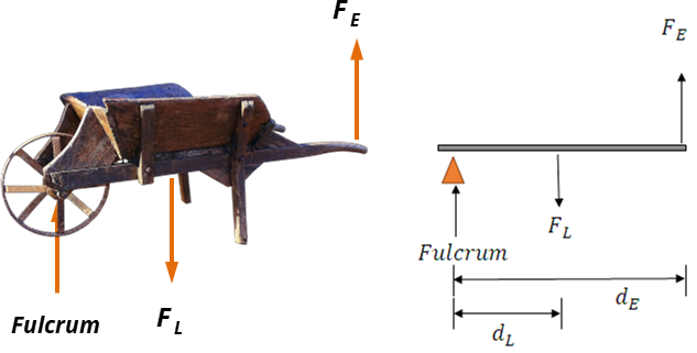
The material (e.g. soil, rocks, roof shingles) would be placed in the wheelbarrow to provide the load force. This force would be the weight of the material directed down and causing the wheelbarrow to rotate clockwise around the fulcrum. The effort force needed to lift the material is provided by the user. The effort force would be directed up, causing the wheelbarrow to rotate counter-clockwise. The fulcrum in this example is the wheel.
Third-Class Lever
A third-class lever is a lever with the load force and the fulcrum located on opposite sides of the effort force. These levers require a larger effort force to move a smaller load force. Then why would you want to use them? A third-class lever is beneficial when speed and a larger load arm movement is desired.
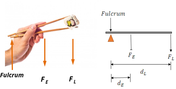
The hand shown in this photo is applying the effort force over a very small effort arm distance to move the chopsticks up and down a larger load arm distance to pick up food. The food in this example is providing the load force. Keep in mind, a third-class lever is used when speed is desirable. This is why chopsticks make a perfect machine to use for eating.
Pulleys
A pulley is a member of the lever family and is a simple machine that has a rope which passes over a wheel that rotates around a central fulcrum. The diagram below illustrates why a pulley is considered part of the lever family.
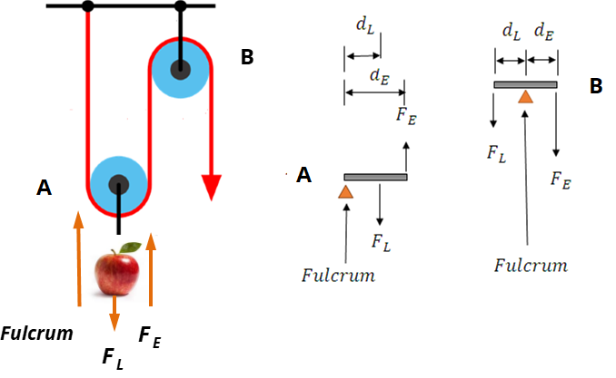
Do you notice any differences between these two pulleys? What is the load force? Where is the effort force located? Are the fulcrums located in the same location for each pulley?
Let’s analyze! We simplify our analysis by ignoring the mass of the pulleys. The pulleys in each of these photos have fulcrums located in two different locations. Pulley A is an example of a second-class lever and is free to move when an effort force is applied upwards on the rope. The weight of the apple provides the load force and the fulcrum is located at the end of the pulley closest to the fixed end of the rope.
Pulley B is an example of a first-class lever. Both the effort force and load force are on opposite sides of the fulcrum.
Where are the effort arm and load arms for each pulley? The effort arm and load arm for pulley B is equivalent to the pulley’s radius. This is not the same for pulley A. The effort arm in this case is equivalent to the pulley’s diameter and the load arm is equivalent to the pulley’s radius.
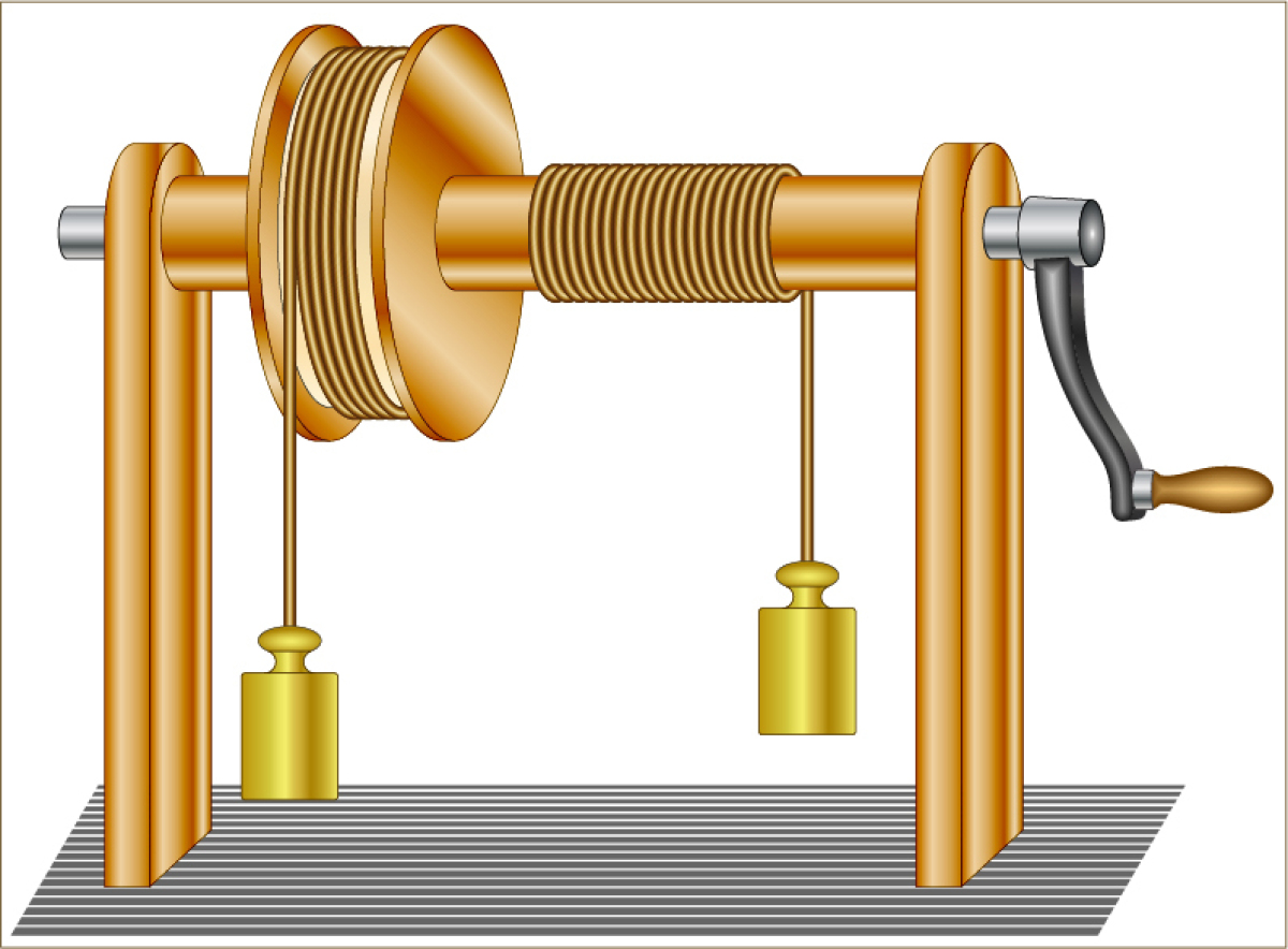
Wheel and Axle
A large disc (wheel) is connected to a smaller disc/rod (axle) that rotate simultaneously around a central fulcrum much the same as a pulley does. An effort force is applied to the wheel to rotate the axle or vice versa. A load is often attached to the axle using a rope or chain.
Gears
Gears are toothed wheels. They are used to accomplish the following:
- Increase Speed
- A larger toothed-wheel connected to a smaller toothed-wheel will cause the smaller toothed-wheel to rotate faster.
- Increase Force
- A larger toothed-wheel will turn slower than the smaller-toothed wheel but with a greater effort force.
- Change Direction
- Toothed-wheels that are part of a system will rotate in opposite directions. If a one toothed-wheel is rotating to the right, the adjacent toothed-wheel will rotate to the left.
 Investigating Levers
For this learning task, you will find examples of levers in your own home and determine the location of the fulcrums, effort force, load force, effort arm, and load arm for each.
For each lever, you will:
- Take a picture or draw a sketch of the lever.
- State the lever’s purpose.
- Determine which of the five main functions of simple machines the lever fulfills.
- Label the load arm, effort arm, load force, effort force, and fulcrum.
- Determine if it is a 1st class lever, 2nd class lever, or 3rd class lever.
Torque
Torque is a measure of the rotational force of a rigid body about an axis of rotation (fulcrum) caused by a force, F, applied a distance, d, from the fulcrum.
As you observed in the assignment above, the magnitude of the torque (i.e. rotation) is directly proportional to the magnitude of the applied force, and the magnitude of the applied force is inversely proportional to the length of the force arm. These relationships can be represented mathematically as:
![[?][?]=Fdsin[?][?]](_images/image_4opBB.gif)
Where,
![[?][?]](_images/image_mOjWY.gif) = torque is meansured in
= torque is meansured in 
 = applied force measured in newtons,
 = force arm measured in metres,
![[?][?]](_images/image_gtXMb.gif) = the angle made between the direction of the force and the direction of the force arm
= the angle made between the direction of the force and the direction of the force arm

The wrench diagram illustrates that the component of the distance, d, varies according to the angle at which the force is applied on the wrench (rigid body). For the purposes of this course, we will only consider situations when the force is applied at a 90° angle to the force arm; therefore, since  90°=1 we can restate the formula as:
![[?][?]=Fd](_images/image_OPHGl.gif)
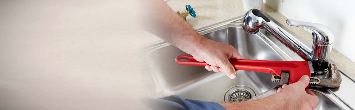
The photo above shows a common pipe wrench that is generally used to tighten and loosen pipe fittings that require much more torque than can be applied by hand.
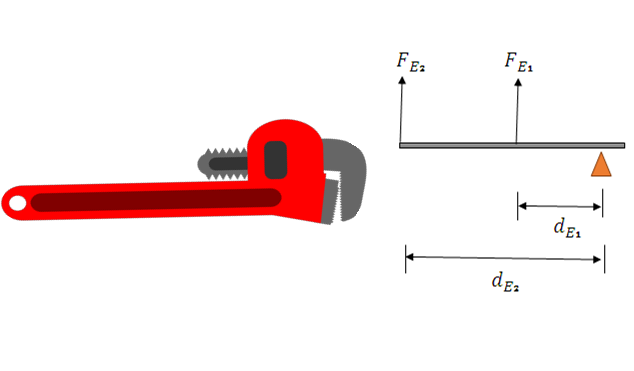
Let’s analyze the optimal position to place our hand on the pipe wrench shown above. Our effort force of  , will remain constant. If the effort arm,
 is 24 inches and the effort arm,
 is half of that, determine the torque caused by the effort forces,
 and
and
 respectively.
Given:

Required:
We are asked to determine the torque for  and
and  .
.
![[?][?]_{1}=?](_images/image_tTmYN.gif)
![[?][?]_{2}=?](_images/image_lRtlL.gif)
Analysis:
Both effort forces will cause the wrench to rotate clockwise around the fulcrum. We need to convert the effort arm to S.I. units before calculating torque.
Solution:
We will first convert the units of the effort arm from inches to metres.
 Next, we will calculate the torque for each effort arm location.
![[?][?]_{1}=Fd](_images/image_Vhcxe.gif)
![[?][?]_{1}=(98N)(0.6096m)](_images/image_yv5ik.gif)
![[?][?]_{1}=59.7408Nm](_images/image_9QX9l.gif)
![[?][?]_{2}=Fd](_images/image_FgmRI.gif)
![[?][?]_{2}=(98N)(1.2192m)](_images/image_eiw8l.gif)
![[?][?]_{2}=119.4816Nm](_images/image_XIxzE.gif)
Paraphrase:
The torque at  is
is  and the torque at
  is
is  . As what is expected, the torque doubled as the effort arm distance doubled so long as the effort force remained constant; therefore, we can conclude that as effort arm increases, the amount of torque increases by the same factor so long as effort force remains the same.
Our calculations have demonstrated that more torque is created the farther the effort force is applied from the fulcrum; therefore, the wrench should be held near the end of the handle.
The Law of the Lever and Static Equilibrium
Recall your Minds On reflection at the beginning of this activity. What similarities and differences did you notice about the two pictures? What did you suggest would cause both of them to collapse?
Consider the diagram below.
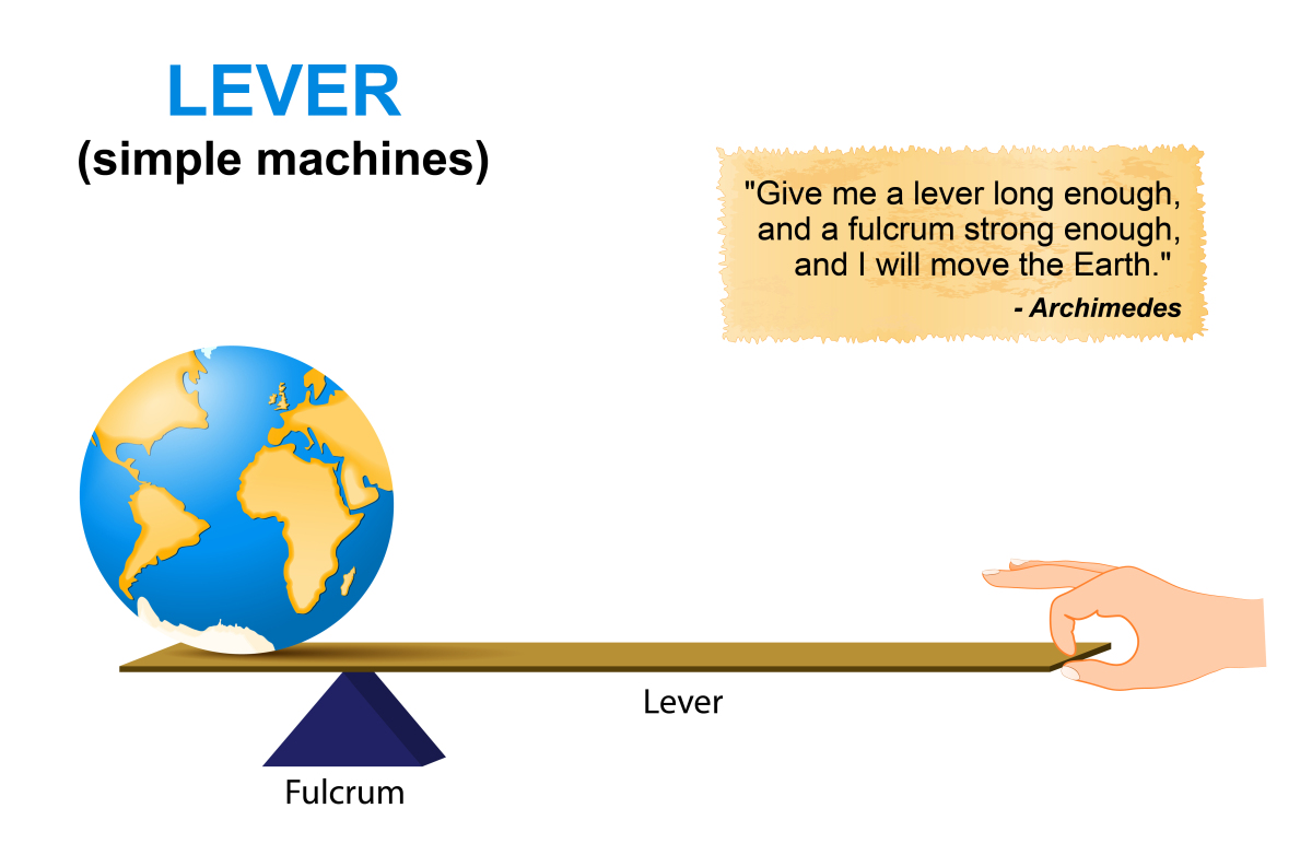
Archimedes determined for a lever to remain at rest or at static equilibrium (balanced), the torque caused by the effort force must be equal to the torque caused by the load force.
Mathematically, this is expressed as:
![[?][?]_{E}=[?][?]_{L}](_images/image_cLZF2.gif)

Let’s consider the situation below.
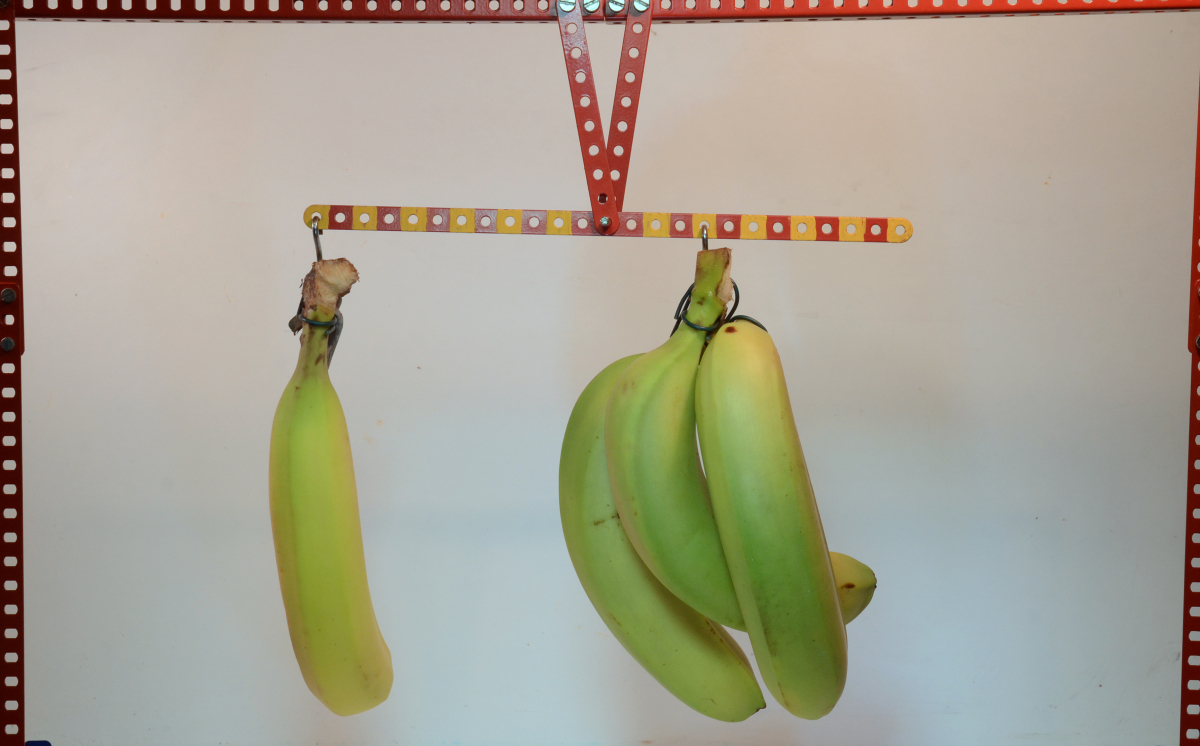
If each yellow and red square on the metal rod is 2.5 cm, prove the equation for the law of the lever is valid in this situation. What would the average mass of each banana have to be to maintain static equilibrium?
Let’s say that the group of three bananas is providing the load force and the single banana is providing the effort force.
Given:
length of each square = 2.5 cm
Required:
average mass of one banana = ?
Analysis:
The effort arm and load arm are calculated by counting the amount of coloured squares and multiplying this by 2.5 cm. Keep in mind that the point where the bananas are hanging and the fulcrum is in the middle of one square.
The effort and load forces are unknown, but recall, the weight of the bananas is equal to the force of gravity on each of their masses.
The system is in static equilibrium, which means that the torque caused by the effort force and the torque caused by the load force must be equal because the system is not rotating.
![[?][?]_{E}=[?][?]_{L}](_images/image_FBR4I.gif)

Let 
 be the average mass of one banana; therefore, the weight of each banana is

Solution:
We will first determine our effort arm and load arm.
Next, we will set up the equation for effort force and load force.

The load force is a multiple of 3 of the effort force because there are three bananas.

Use the law of the lever equation to demonstrate that the effort torque and load torque are equal.
![[?][?]_{E}=[?][?]_{L}](_images/image_TbJAx.gif)

Divide both sides by  .
.


Next, determine the average mass of one banana if the torque that causes the system to rotate counter-clockwise is  .
.
![[?][?]_{E}=m_{E}gd_{E}](_images/image_queVP.gif)
![m_{E}=\frac{[?][?]_{E}}{gd_{E}}](_images/image_HbEy5.gif)
Paraphrase:
The law of the lever holds true for this system that is not rotating and in static equilibrium. The average mass of one banana is 0.15 kg.
Mechanical Advantage
In the real-world, friction plays a pivotal role in the efficiency and the advantage we get from using a machine such as a lever. Over time, friction increases due to wear and tear and if a machine is not properly maintained, it may not serve its purpose and may need to be replaced.
In the banana situation above, we can calculate the actual mechanical advantage (AMA) of the machine by comparing the effort force (input force) to the load force (output force).
Mathematically, this is expressed as

This ratio is a unitless calculation and gives us an idea of how efficient our machine really is.
Let’s calculate the AMA for the banana lever.

This tells us that the lever enables us to lift 3.0 times the amount of load force for every  of effort force.
Biomechanical Machines and Actual Mechanical Advantage
The most common machines that we use in our lives are our own bodies. The body is made of many levers that help us accomplish various tasks throughout the day. The diagram below shows an example of a 1st class lever, a 2nd class lever, and a 3rd class lever in the body.
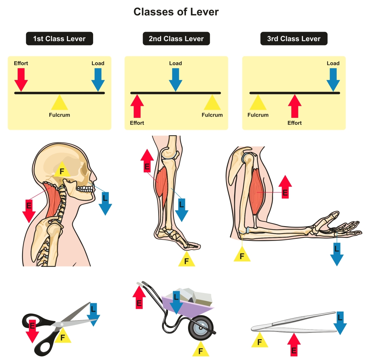
The Body as a 1st Class Lever
Recall a first-class lever is used when a small amount of effort force is required to lift a large load force. The average mass of the human head is 5 kg. Most of the gross motor movement and the responsibility for holding the head up relies on the sternocleidomastoid and the trapezius muscles that are part of the muscular system of the head and neck. These muscles are considered to have the greatest amount of endurance in the body because they never get to rest. Even when you are sitting or lying down, in most cases, these muscles are flexing, extending, rotating, and contracting to control the movement of the head.
The Body as a 2nd Class Lever
The main calf muscles or more scientifically named the gastrocnemius and soleus muscles convert stored chemical potential energy and elastic energy in your cells to kinetic energy to move your feet and ankles so that you can run, jump, pivot, and execute other quick movements that require the legs. The nervous system is always receiving information about the body’s centre of mass and is constantly adjusting these various muscles to keep the body balanced when you are walking, standing, jumping, and running. If these muscles are overworked or are too weak, injury to the ankles and the knees will likely occur.
A person’s ability to jump high or pivot quickly is related to the speed at which elastic potential energy is released and converted to kinetic energy and the explosive effort force that is applied by the calves (along with other muscles) to move the load force (your body) off the ground.
The Body as a 3rd Class Lever
The biceps brachii (the biceps) are generally used to move the forearm when lifting is required. The bicep applies a large effort force over a smaller distance to lift a smaller load force a larger distance. This is why it is important to have strong biceps. In order to lift an object, the bicep must apply a much larger effort force than the load force. Biceps are also involved with the shoulder and elbow joints when lifting. For this reason, bicep weakness can affect the shoulder function.
CONSOLIDATION
Summary
Levers can be classified into three different classes and can be found in your homes and in biomechanical systems.
Biomechanical systems are complex machines that make use of forces and mechanical advantage to allow you to jump, run, chew, walk, and pivot.
Torque is a measure of the amount of rotation caused by a force applied a distance from a central axis (fulcrum).
The law of the lever states that a lever will maintain static equilibrium if the magnitude of the torque created by the effort force, and the magnitude of the torque created by the load force are equal.