Simple Machines
Pulleys and Inclined Planes
MINDS ON
 Reflection
Watch the video below about the block and tackle system and create a reflection to answer the following questions:
- What is the main purpose of a block and tackle system?
- How did the presenter determine the mechanical advantage of the simple pulley system?
- What would cause the block and tackle system’s mechanical advantage to decrease?
ACTION
Inclined Plane Family
Did you know that an axe and a screw are examples of an inclined plane? An inclined plane is a flat ramp inclined at an angle so that one side of the ramp is higher than the other.
Inclined Plane
Inclined planes are a machine that provide a mechanical advantage because they require less effort force from the user to move a load up or down the inclined plane (i.e. ramp) than if the same load was moved directly up or down the height of the ramp.
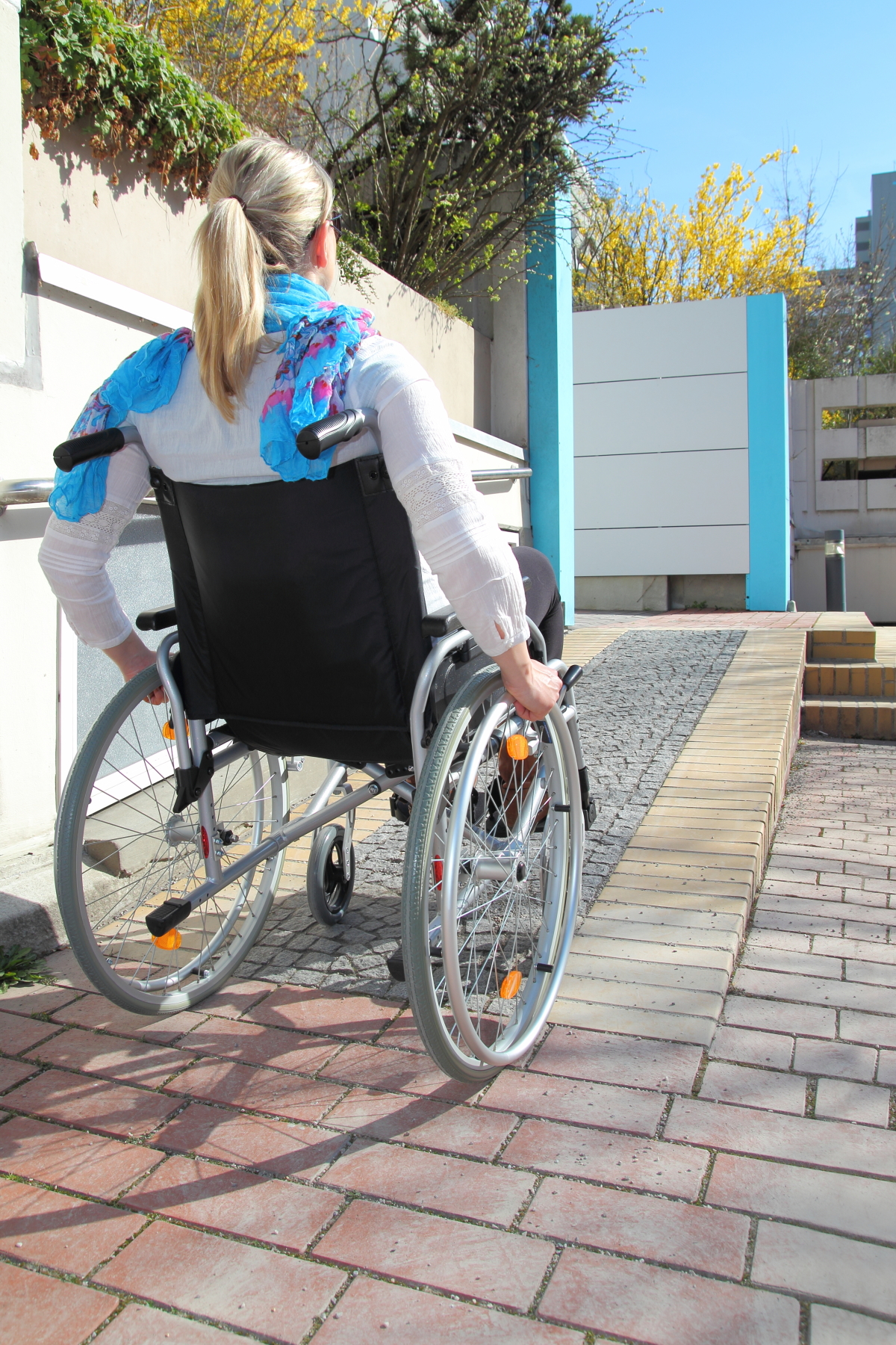
An example of an inclined plane is a wheelchair ramp. A wheelchair ramp requires much less effort force required to be input by the user to move up the length of the ramp than if the same person had to lift themselves up the height of the ramp.
Wedge
A wedge is a double-sided inclined plane that produces perpendicular output forces that enable the simple machine to cut through a hard material such as wood and metal. Examples of wedges include, but are not limited to axes, chisels, and yes, even golf clubs!


Screw
A screw is a double-sided inclined plane wrapped around a cylindrical shaft (fulcrum). The screw produces perpendicular output forces that enable it to penetrate the material easily.

Ideal vs. Actual Mechanical Advantage
The law of the lever states that for a lever in static equilibrium, the magnitude of the torque created by the effort force equals the magnitude of the torque created by the load force. This law can be mathematically represented as follows:
If we rearrange the formula and set up two ratios that compare the forces to the arms we will have:

Ideally, the ratio of the effort force to the load force should equal the ratio of the load arm to the effort arm. Unfortunately, this is not always the case. Over time, a machine is subjected to wear and tear and if it is not maintained properly, the friction forces between its parts will increase. An increase in friction will require an increase of the magnitude of the effort force needed to move the same magnitude of the load force. Think of it this way – if a pulley is well lubricated, the fulcrum moves freely and the effort force needed to move the load force is quite low. If the pulley is not lubricated, friction increases and the amount of effort force needed to move the same load force increases, as well.
We know that the actual mechanical advantage (AMA) of a machine is calculated by using the following mathematical equation:

This is the “actual” mechanical advantage you “do” receive from the machine.
Mathematically, we can calculate the ideal mechanical advantage (IMA) of a machine by comparing the ratio of the effort arm to the load arm in the equation below.

This is the “ideal” mechanical advantage you “should” receive from a machine. In other words, this is the mechanical advantage you are ideally supposed to get from the machine.
The IMA of various simple machines is shown in the following table.
| Simple Machine | IMA |
|---|---|
| Inclined Plane | 
|
| Set of Pulleys | number of "support strands" |
| Set of Gears | ratio of the teeth in the gears 
|
| Wheel and Axle | ratio of the radii 
|
Useful energy is the amount of energy that is used to accomplish a specific task. For example, powering the motor in a vehicle, emitting light from a lightbulb, and radiating thermal energy (heat) from a furnace. If a machine experiences no useful energy loss due to friction, then we can say that 
 and
and

Waste energy is the amount of energy that is wasted from a machine that is NOT used to accomplish a specific task. For example, emitting thermal energy from a photocopier and creating sound energy when blending food in a food processor. In all of these examples, the “waste energy” is not used but is a by-product of the machine’s purpose or process. If a machine has to reduces the useful energy output due to friction, then 
 and
and

 Example
Given:
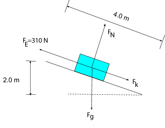
length of the inclined plane = 4.0 m
height of the inclined plane = 2.0 m


Required:


Analysis:
Let’s draw a system diagram so that we can analyze the situation in more detail.
Solution:
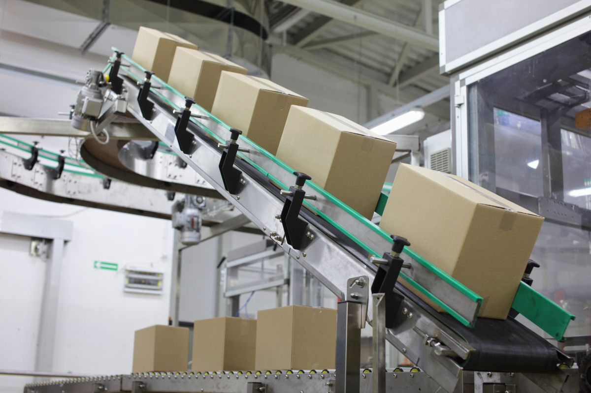
First we will find the amount of force that would be needed to lift the box vertically without the use of the conveyor belt. In other words, we need to find the amount of force needed to lift the box straight up 2.0 m. This is our output or load force and it is equivalent to the box’s weight. For this reason, we need to calculate the magnitude of the force of gravity on the box as shown below.


Since we already know that the effort force to slide the box up the ramp is 310 N, we can calculate the actual mechanical advantage now by dividing the load force by the effort force.

To calculate the IMA of an inclined plane, we need to find the ratio of its length to its height; therefore


Paraphrase:
The AMA for the conveyor belt is 1.7 and the IMA is 2.0. The IMA tells us that, “ideally” for every 1 N of force input by the user, 2.0 N of force is output.
 The Role of Friction
Why did the actual mechanical advantage not yield the same result as the ideal? This is due to friction. The effort force must increase to account for the added kinetic friction force (because the box is moving) opposing the motion. Conveyor belts are made of materials that increase the amount of friction between the belt and the objects being moved.
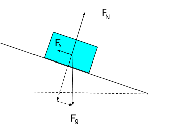
Think about this: In the real-world, we do not want objects sliding down a conveyor belt; therefore, the magnitude of the component of the gravitational force that would pull the box down the conveyor must be equal and opposite to the magnitude of the static friction force opposing the motion and preventing the box from moving and keeping it at rest on the belt. Remember, if an object is at rest and not moving, then all of the forces acting on the object must add up to zero.
The free-body diagram provides an illustration of all the forces acting on a box when it is sitting on a conveyor belt. Notice that the force of friction and the component of the force of gravity parallel to the ramp are equal in magnitude but opposite in direction; therefore, they sum to zero. Additionally,the normal force and the component for the force of gravity perpendicular to the ramp are equal but opposite in direction and sum to zero. All the forces sum to zero. The box remains at rest according to Newton’s first law of motion.
Let’s calculate the amount of work done to push the box up the conveyor as opposed to lifting it straight up the same height. Assume the coefficient of kinetic friction is 0.075.
Recall, the amount of work done by you to push the box up the conveyer is equal to the amount of kinetic and chemical potential energy in your cells transferred to the box in the form of kinetic energy and gravitational potential energy.
Given:
length of the inclined plane = 4.0 m
height of the inclined plane = 2.0 m


Required:
Work done by sliding the box up the conveyer =?
Work done by lifting the box up the height of the conveyor=?
Analysis:
Let’s draw a free-body diagram and look at all the forces that are involved in calculating work in this situation. Let the direction up the conveyer be the positive x-direction.
The law of the conservation of energy states that energy is always conserved; therefore, the work done by sliding the box up the conveyor should equal the same amount of work done to lift the box up the conveyor height. Remember, energy cannot be created or destroyed, it can only transform from one form to another.
Solution:
First, we need to find the amount of work that is done to slide the box up the length of conveyor. Remember, the force of friction does negative work on the box.


Next, we’ll find the amount of work that is done to lift the box up the height of the conveyor.

Paraphrase:
The amount of work done to push the box up the conveyor is  which is equal to
  of work done to lift the box up the height of the conveyor.
According to the law of the conservation of energy, energy cannot be created or destroyed; therefore, the amount of work done has to be equal in both cases.
Calculating the IMA for Wheel and Axles, Gears, Pulleys
Let’s try a few more examples of calculating the ideal mechanical advantage for other types of machines.
Vehicles are an example of a very complex compound machine. Gears transfer mechanical energy from the crankshaft (axle that rotates due the transfer of chemical potential energy to kinetic energy from the engine) to the crankshaft that rotates the wheels.
One purpose of a gearbox in a vehicle is to increase the amount of force provided by the engine while you are in low-gear to start the motion of your car while reducing the speed of the vehicle. If the this wasn’t the case, then your vehicle would take off like a bullet the moment you started to move. When a vehicle is in high-gear, the force from the engine is used to increase the speed at which time the wheels turn and ultimately increase the speed of the vehicle.

 Practice
Calculate the IMA of the interlocking gears shown above if the larger wheel is turning the smaller wheel. For this problem, we will need to count the “teeth” on each gear.
Solution
Given:


Required:

Analysis:
The larger toothed-wheel is turning the smaller toothed-wheel. This means that the larger toothed-wheel is turning slower and applying a greater effort force to the faster turning smaller toothed-wheel.
Solution:


Paraphrase:
Therefore, the ideal mechanical advantage provided by the gear system is 1.3. This means that for every 1 N of force input by the larger gear, 1.3 N of force is output by the smaller gear.
Observe the following diagram of the pulley systems.

Pulley systems rely on the number of support strands that support the load force in order to increase their ideal mechanical advantage. The first pulley on the left only has one support strand; therefore, this pulley does not multiply and provide a mechanical advantage. It does however change the direction of the force.
The second pulley system from the left has two support strands; therefore, it doubles the load force. This means the effort force is halved for every 1 N of load force. This pulley also changes the direction of the force.
The third pulley system from the left has three support strands; therefore, it triples the load force. This means the effort force is divided into thirds for every 1 N of load force. This pulley also changes the direction of the force.
The fourth pulley has four support strands; therefore, it multiples the load force by four. This means the effort force is divided into fourths for every 1 N of load force. This pulley also changes the direction of the force.
 Questions
Try the following questions on your own, and then check them to see how you did. Make sure you express each answer to the correct number of significant digits.
- Calculate the IMA of the inclined plane shown.

- 3.3
- 0.3
- 3.5
- 18
c. 3.5


-
Hydroelectric dams make use of gravitational potential energy and kinetic energy of falling water to turn a large wheel turns a turbine in order to generate electrical energy that can be sent to the power grid and used by society. What is the IMA of the wheel and axle shown?
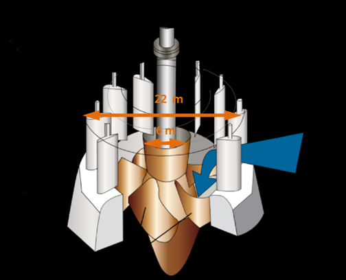
- 3.7
- 0.27
- 7.3
- 4
a. 3.7


- Gears are often connected to each other by a chain. Calculate the IMA of the system below knowing that a bicycle’s pedals are connected to the large gear.
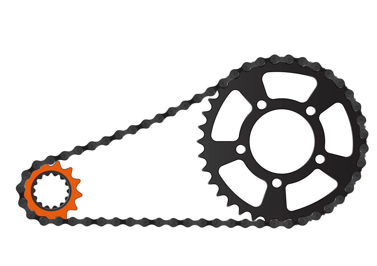
- 2.7
- 2.8
- 0.36
- 0.4
a. 2.7


 Investigate the IMA of Household Items
For this learning task, you will find at least five (5) various machines that are included in the lever and inclined plane families and determine their ideal mechanical advantages using measuring devices you have available at home (i.e. rulers, tape measures etc.).
For each machine you will:
- Take a picture or draw a sketch of the machine.
- Measure and record the quantities needed to determine the IMA.
- Provide all calculations for each machine.
CONSOLIDATION
Summary:
The actual mechanical advantage, AMA, of a machine can be calculated by finding the ratio between the effort force (input force) and the load force (output force). This is the mechanical advantage that you “do” receive from a machine.

The ideal mechanical advantage, IMA, of a machine can be calculated by finding the ratio between the load arm and the effort arm. This is the mechanical advantage that you “should” receive from a machine.


If the effort force must increase to account for an increase in friction between the parts of the machine, then the actual mechanical advantage will calculate to less than the ideal mechanical advantage.


The IMA of various machines can be calculated in various ways. The following table provides a summary of the IMA calculation methods for various simple machines.
| Simple Machine | IMA |
|---|---|
| Inclined Plane | 
|
| Set of Pulleys | number of "support strands" |
| Set of Gears | ratio of the teeth in the gears 
|
| Wheel and Axle | ratio of the radii 
|