Hydraulics and Pneumatics
Hydraulic Systems
MINDS ON
 Reflection
Create a reflection to answer the following questions:
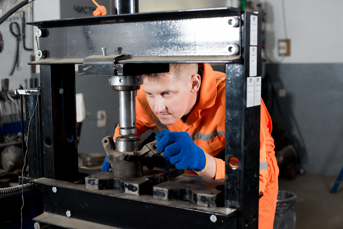
- What might be some more practical purposes for a hydraulic press, other than crushing things for entertainment?
- What other hydraulic systems can you think of? Where and how are they used?
ACTION
Hydraulic Systems
A hydraulic system is one that uses an incompressible fluid (a liquid) to transmit and control pressure, which can be turned into a force to accomplish useful work. Hydraulic systems are used in everything from heavy construction equipment to industrial robots to jacks and hoists to automobiles. Because hydraulic systems use an incompressible fluid, they are able to control the position of objects very exactly.
Hydraulic systems need an incompressible fluid to operate. This fluid may be liquid water but it is more common to use oil as the fluid in a hydraulic system. Beyond being incompressible, a hydraulic fluid should usually be a good lubricant, as many hydraulic components contain moving parts, and depending on the application, special properties such as low combustibility or biodegradability.
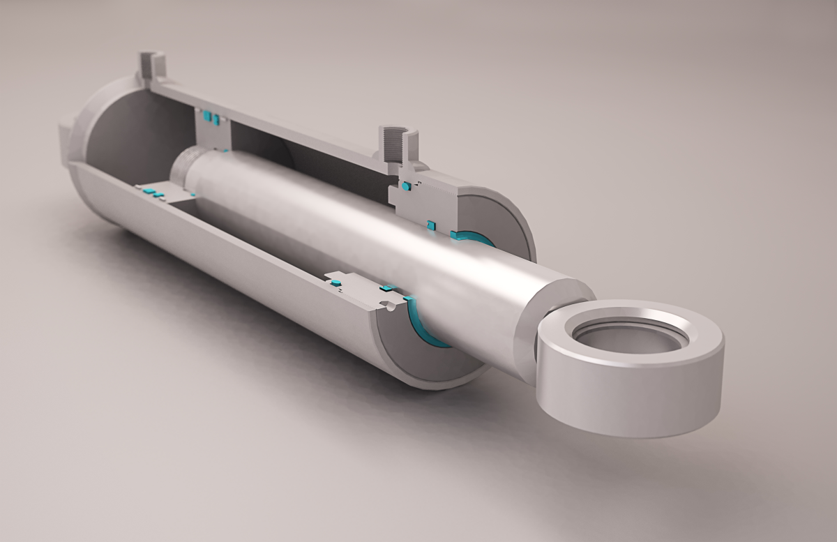
The Cylinder
The cylinder is a key component of almost any hydraulic system. The function of the cylinder is to provide a way to transform force and motion into pressure and the flow of hydraulic fluid and vice-versa. Key parts of a hydraulic cylinder include:

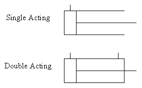
The ports allow hydraulic fluid to flow in and out of each end of the barrel while the piston and rod slide back and forth in the barrel. The cylinder in the diagram is a double-acting cylinder because it has a port at each end of the barrel. Single-acting cylinders only have a port at one end of the barrel, and are open to the air at the other end (no hydraulic fluid is present on the non-ported side of the piston in a single-acting cylinder).

Where A is the area of the piston head in square metres and r is the radius in metres. Another equation will also be useful for calculating the volume of a cylinder:

Where V is the volume of the cylinder in cubic metres, r is the radius in metres and h is the height in metres. Note that this equation applies to any cylinder shape, not just a cylinder in a hydraulic system. It can also be used to calculate, for example, the volume of hydraulic fluid that would be displaced as a piston moved over a distance h.
The Pump
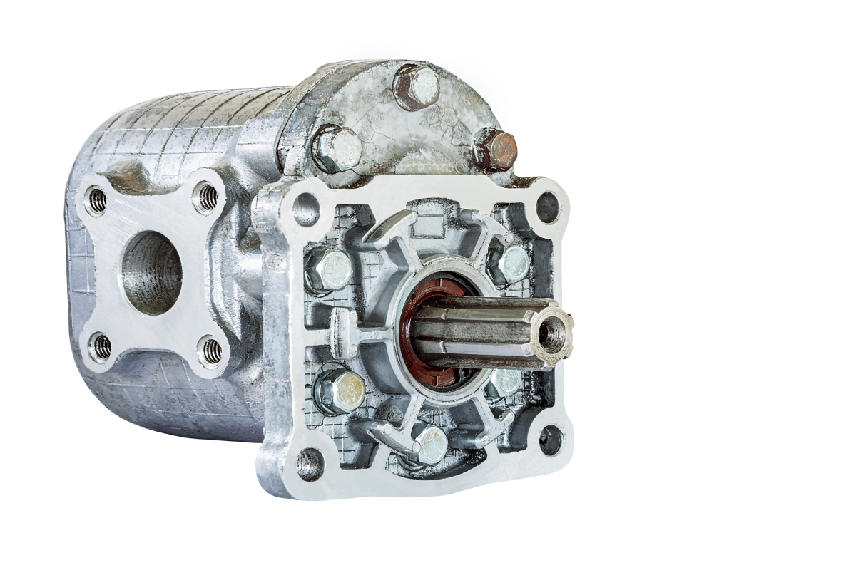
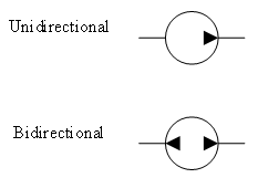
A pump transforms mechanical energy into pressure and the flow of hydraulic fluid. In the simplest possible hydraulic system, a pump is connected to a double-acting cylinder by two transmission lines. This system is represented in the diagram below, where the pump is represented by a circle with an arrow, to indicate the direction of flow of the hydraulic fluid. Since hydraulic fluid is being pumped into the left port of the cylinder, the piston and rod will be pushed to the right.

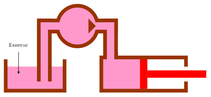
The Reservoir
Many hydraulic systems do not contain a closed loop like the pump with the double action cylinder. Instead, these systems might use a single action cylinder. In many cases, these systems will use a reservoir to store hydraulic fluid to be pumped into a cylinder and recover it when it is forced out. There are two main types of reservoir: those that are open to atmosphere (as shown in the diagram) and pressurized reservoirs.
Additional Hydraulic System Components
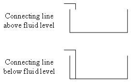
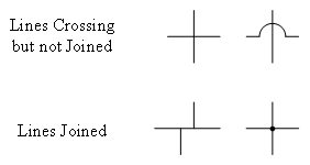
Transmission lines, already mentioned, transmit pressure and the flow of hydraulic fluid around a hydraulic system. Hoses and tubing are typically used as transmission lines in hydraulic systems.
Fittings and connectors are used to connect transmission lines to various system components.
Motors are used to supply mechanical energy to a pump.
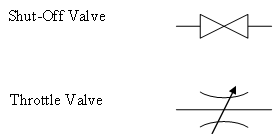
Valves act like switches and are able to allow or block the flow of hydraulic fluid through a transmission line. These can be controlled by a person or computer, or may be automatic in their operation. For example, a safety valve may automatically open if the pressure becomes too high.
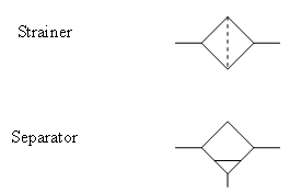
Filters remove debris from hydraulic fluid in order to reduce wear on other system components, such as pumps, that would be expensive to repair.
Hydraulic System Symbols
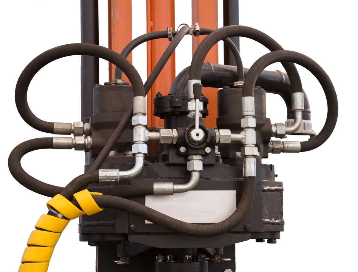
When designing hydraulic systems, it can get tedious to draw each component of the system as it would appear in the final system. Consider how much time a designer might spend drawing the pump depicted in the image. Instead of drawing components the way they really look, designers use symbols to represent them in diagrams. This way, the diagram can be simpler and focus on the function of the components in the system, rather than their appearance. Designers can create a diagram of the system more quickly and then move on to building it sooner. The following table includes symbols for some common hydraulic system components:
| Component | Symbol |
|---|---|
| Cylinder |
|
| Pump |
|
| Reservoir |
|
| Transmission line |
|
| Valve |
|
| Filter |
|
(Volumetric) Flow Rate

A very important concept in hydraulic systems is that of the rate of flow of hydraulic fluid. Rate of flow is analogous to speed in a mechanical system, but it is not the speed at which the hydraulic fluid is moving along a transmission line that is important. Rather, it is the volume of hydraulic fluid that moves through a particular point per unit time. This is known as the volumetric flow rate. The following equation relates volumetric flow rate to volume and time:

Where Q is the volumetric flow rate, V is the volume of hydraulic fluid moved and Δt is the time elapsed.
 Example
A cylinder has a piston head with a radius of 2.5 cm. A force is applied to the rod, which moves a distance of 12 cm in 15 s. What is the volumetric flow rate of hydraulic fluid?
Solution
Given:
r = 2.5 cm = 0.025 m
 = 12 cm = 0.12 m
Δt = 15 s
Required:
We are required to calculate Q, the volumetric flow rate.
Q = ?
Analyze:
The piston has moved a distance of 0.12 m. We must use this to calculate the amount of hydraulic fluid that it displaces.


The volume of hydraulic fluid displaced by the piston is 0.0024  .
.
Solve:

Paraphrase:
The volumetric flow rate of hydraulic fluid is 0.000016  /s.
/s.
 Questions
- A cylinder has a piston head with a radius of 12 cm, which moves 25 cm in 13 seconds. What is the volumetric flow rate of hydraulic fluid?
- 0.087
 /s
/s - 0.72
 /s
/s - 23
 /s
/s - 72
 /s
/s
a. 0.087
 /s
/s
- 0.087
- A cylinder has a piston head with a radius of 7.2 cm and hydraulic fluid flowing into it at a rate of 0.012
 /s. How long does the piston take to move 14 cm?
- 1.9 s
- 2.6 s
- 19 s
- 162 s
c. 19 s
- A cylinder has hydraulic fluid flowing into it at a rate of 0.021
 /s for 22 seconds. What is the volume of hydraulic fluid that entered the cylinder?
- 0.00095

- 0.46

- 1000

- 1047

b. 0.46

- 0.00095
Pascal’s Principle
Blaise Pascal was a mathematician and physicist who determined that if there was an increase in pressure anywhere in a confined fluid, an equal increase in pressure would be transmitted to every other point in the fluid, as well as the walls of the container. Pascal’s principle makes it possible to design hydraulic systems to achieve mechanical advantage.
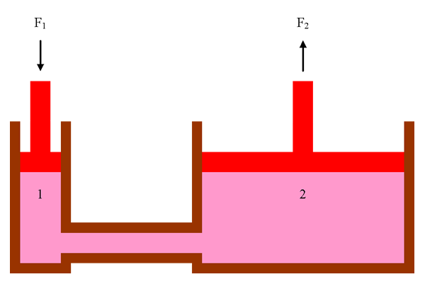
The diagram shows a hydraulic press, with two cylinders (labelled 1 and 2) connected by a transmission line. Pascal’s principle tells us that the pressure in cylinder 1 must be equal to the pressure in cylinder 2 so we can state mathematically:

Since pressure is the ratio of the force applied on each piston per unit of surface area, we can substitute:

This simple relation can be applied to any hydraulic system. By selecting cylinders with the correct ratio between the areas of their piston heads, we can design a hydraulic press with mechanical advantage. It might be simpler to re-arrange the hydraulic press equation to calculate its mechanical advantage:

The ratio in this hydraulic system is analogous to the
 ratio in a simple machine, so
  is the actual mechanical advantage (AMA) of the hydraulic press. Similarly, the ideal mechanical advantage (IMA) for a hydraulic press is
  . According to Pascal’s principle, a small downward force (
 ) on the rod in cylinder 1 results in a large upward force (
 ) being exerted by the rod in cylinder 2, since the area of the piston head in cylinder 2 is greater than the area of the piston head in cylinder 1.
Another important characteristic of a hydraulic press is that the ratio of the distance travelled by each of the rods will be the inverse of the ratio of the area of each of the piston heads. Mathematically, this can be expressed as follows:

In the hydraulic press diagram, the area of the piston head in cylinder 2 is greater than the area of the piston head in cylinder 1. This means that the distance travelled by the rod in cylinder 1 will be greater than the distance travelled by the rod in cylinder 2.
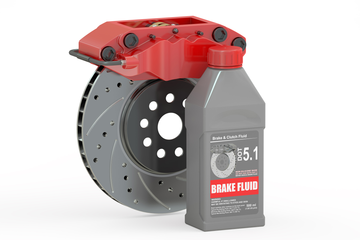
Hydraulic Brakes
Hydraulic brakes are standard on passenger vehicles today. There are two basic types of hydraulic brakes in common use: drum brakes and disc brakes. Both types of hydraulic brake rely on the driver to push on a pedal, which is mechanically connected to a “master” cylinder. This master cylinder converts the pedal push into pressure and movement of hydraulic fluid (brake fluid) in the transmission line (brake line). The difference between drum brakes and disc brakes lies in what happens at the end of the brake line:
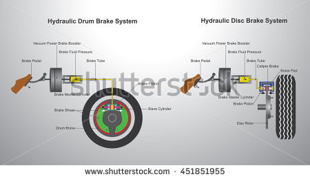
Drum brakes work by using a “slave” cylinder to push apart two “shoes” (semi-circular in shape) inside a brake “drum” that is rotating with the wheel. When the shoes push against the drum, this creates friction and the force of friction between the two slow the rotation of the drum and wheel.
Disc brakes work by using a slave cylinder to push two “pads” on either side of a brake “rotor” (disc-shaped) that is rotating with the wheel. Just like with drum brakes, the force of friction between the pads and the rotor works to slow the rotation of the rotor and wheel.
Disc brakes have better stopping power than drum brakes due to the fact that the rotor is exposed to the outside air while it is rotating. As their name suggests, drum brakes are fully enclosed in a drum-shaped metal housing, which makes it more difficult for a drum brake to dissipate the heat that results from the friction between the shoes and drum. For this reason, disc brakes are typically used on front wheels where the required braking power is higher, while drum brakes are more commonly found on rear wheels. Some sports cars will have disc brakes on all four wheels.
Example
A hydraulic braking system in a car has a master cylinder with a radius of 1.25 cm connected to a slave cylinder with a radius of 2.1 cm. If a force of 410 N is applied to the rod in the master cylinder, what force does the slave cylinder apply to the brake pads?
Solution
Given:
 = 1.25 cm = 0.0125 m
 = 2.1 cm = 0.021 m
 = 410 N
Required:
We are required to find the force the slave cylinder applies on the brake pads, F2.
 = ?
= ?
Analyze:
First, we must find the area of the piston head in each cylinder.


Solve:
Paraphrase:
The force the slave cylinder applies on the brake pads is 1200 newtons.
 Hydraulic Systems in Action
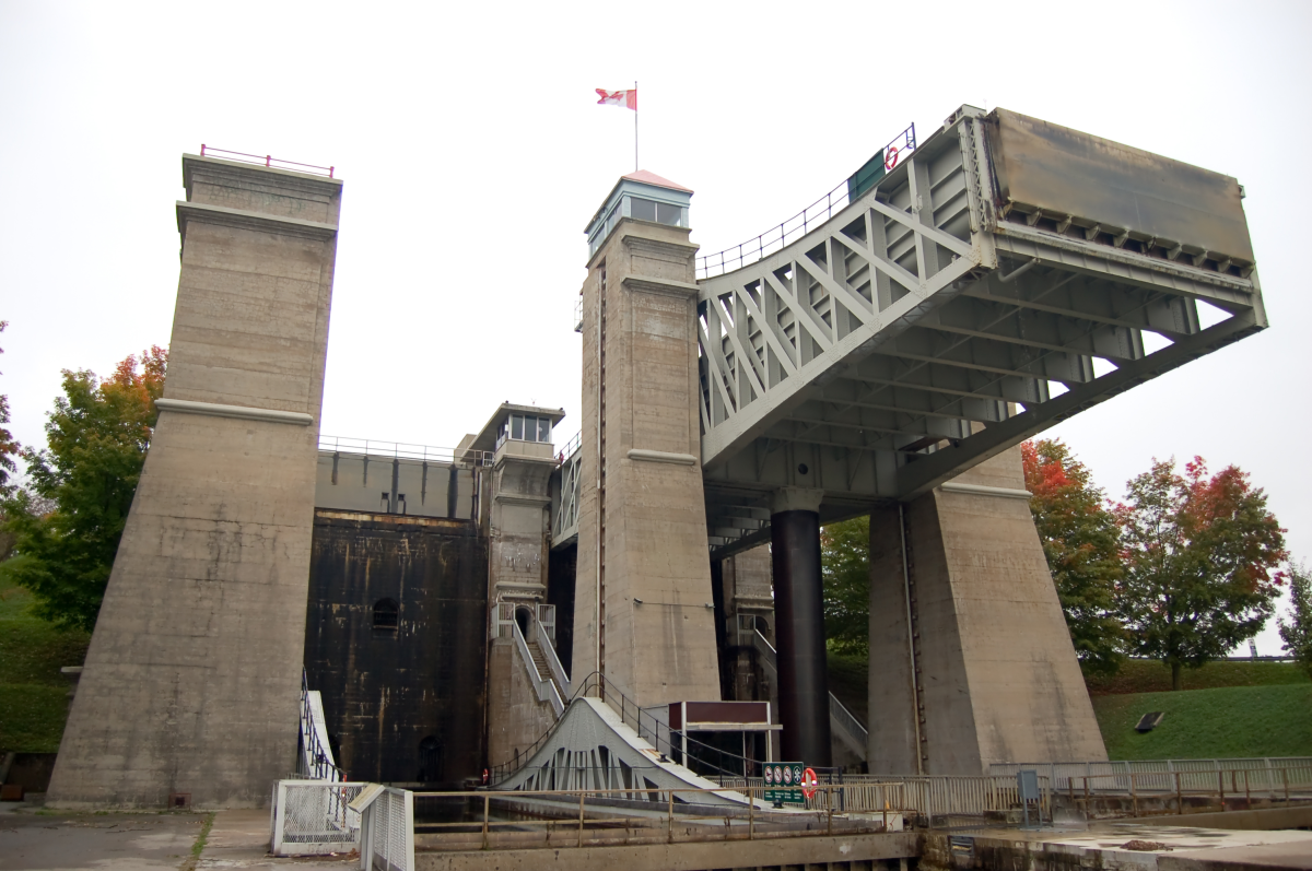
The Trent-Severn Waterway Lift Lock 21, better known as the Peterborough lift lock, was constructed with two caissons (water-tight compartments) atop two large pistons (each with a diameter of 2 m) in the early 20th century. Each caisson is 42.4 m long and 9.7 m wide and fills with water to a depth of 2.1 m. To raise and lower the caissons, the lock operators allow a little more water into the top caisson, making it slightly heavier than the bottom caisson, and a valve is opened between the hydraulic cylinders, allowing hydraulic fluid to move between them. The heavier caisson drops to the bottom position and pushes the lighter caisson to the top position. Each piston travels 19.8 m during this process, which takes about 165 seconds. Next, the valve is closed to lock the caissons in place and the gates are opened to allow the boats in each caisson to access the next stage in the waterway, and to allow waiting boats to enter for the next lock cycle.
 The Use of Robotic Systems

Robotic systems are taking the place of humans in many situations, for example in manufacturing and working with hazardous materials and/or in hazardous locations. For this learning task, you will choose a specific situation where the use of a robotic system can take the place of a human, analyze the social and/or economic consequences, and discuss with your classmates. You should:
- Conduct research about the robotic system application.
- Provide a description of your chosen robotic system.
- Provide specific examples of impacts that the use of your chosen robotic system will have on people and/or the economy.
- Indicate whether each impact is positive or negative and explain your reasoning.
 Careers
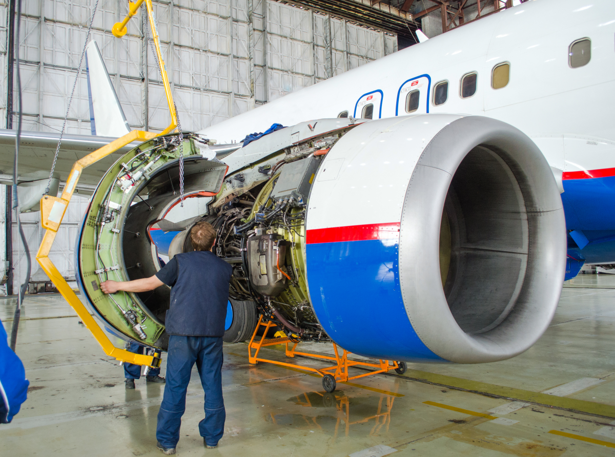
An Aircraft Mechanic is responsible for ensuring that an aircraft is maintained in a condition that is safe to fly. They perform routine maintenance tasks, inspect components regularly, and conduct emergency repairs when equipment fails unexpectedly.
An Aircraft Mechanic may work on equipment such as avionics (electronics like the radio and flight instruments), engines, flight controls systems (utilizing hydraulic systems), airframe maintenance, electrical systems, and more. Aircraft Mechanics may work for a large airline or for a smaller business that services aircraft owned by different entities. Work may be performed indoors or outdoors, and can be very physically demanding as it can be difficult to access all areas of an airplane that require maintenance.
Find out more about becoming an aircraft mechanic at avjobs.com.
CONSOLIDATION
Summary
Hydraulic systems are constructed from a combination of these components:
- Cylinders (key property is the area of the piston head)
- Pumps (key properties are the pressure created and the volumetric flow rate)
- Reservoirs
- Transmission lines
- Fittings and connectors
- Valves
- Filters
The volumetric flow rate is the volume of fluid that passes a particular point in a system per unit time, and can be calculated using the following equation:

Pascal’s Principle tells us that an increase in pressure at any point in a closed hydraulic system results in an equal increase in pressure at all other points in the system. When applying Pascal’s Principle to a hydraulic press, the following equation relates the area of each piston head to the force acting on each rod:

For a hydraulic press, the ratio A2/A1 is its ideal mechanical advantage (IMA); the ratio F2/F1 is the actual mechanical advantage (AMA). The following equation relates the area of each piston head to the distance travelled by each piston in a cylinder:
