Hydraulics and Pneumatics
Pneumatic Systems and Fluid Dynamics
MINDS ON
When designing transportation systems like planes, trains, automobiles, and ships, engineers always look for ways to reduce friction to increase the speed and efficiency of the vehicle they are building. Friction can arise in several forms: static, kinetic, and rolling friction, as well as drag (better known as air resistance in the case of vehicles travelling through the air).
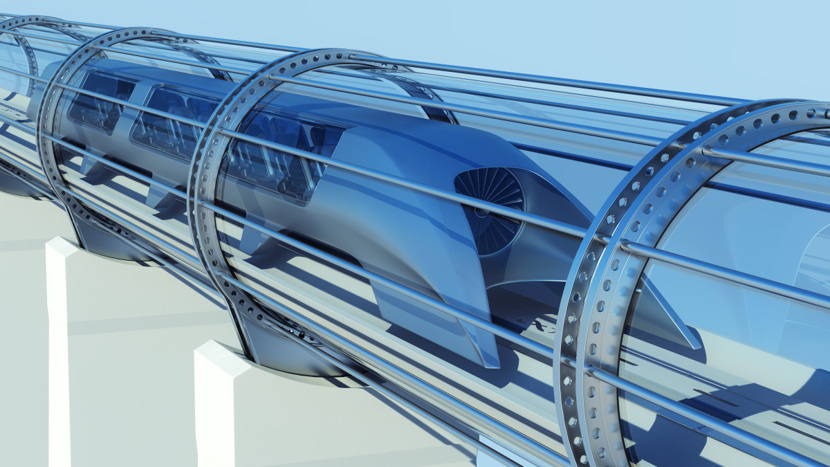
First, to reduce friction resulting from wheels rolling on a track, the hyperloop capsule does away with wheels entirely. Instead, it incorporates an air compressor that delivers a supply of pressurized air to a series of air bearings, which maintain a thin layer of pressurized air between the track and the capsule supports, allowing movement with virtually no friction between the capsule and track.
Second, to reduce drag, more pumps are used to draw air out of the tube, reducing the pressure in the tube as well as the density of the air. This results in very low drag, since there are fewer air molecules to impede the motion of the capsule.
It is believed that a hyperloop system, if constructed, could support capsule speeds near 1000 km/h, faster than any common existing mode of transportation, including passenger jets.
 Reflection
Create a reflection to answer the following questions:
- Which aspects of the hyperloop concept have safety or security implications? How do these compare in other transportation systems?
- How might society be changed by the development of hyperloop transportation on a large scale?
ACTION
Pneumatic Systems
Just like hydraulic systems, pneumatic systems use a fluid to transmit and control pressure, which can be turned into a force to accomplish useful work. While hydraulic systems use an incompressible liquid, pneumatic systems use a compressible gas (usually air).

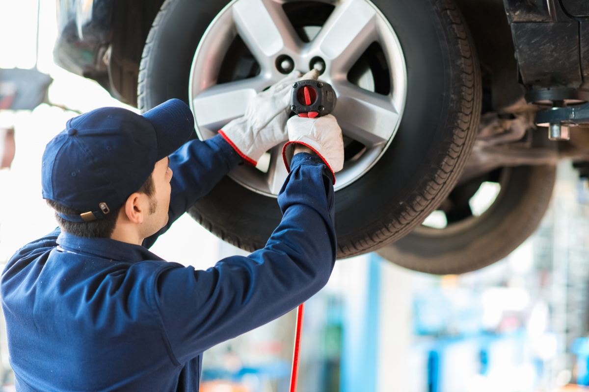
Pneumatic systems use many of the same components that hydraulic systems do including cylinders, transmission lines, fittings, valves and filters. Instead of a hydraulic pump, a pneumatic system uses an air compressor to transform mechanical energy into a higher fluid pressure. Pneumatic systems also include a type of reservoir, but, because gases need to be fully contained, a pressurized tank is used to store the compressed gas from the compressor until it is needed. In many cases, the compressor and tank are built as a single combined unit, so that they can be easily repositioned in an automotive repair shop, for example.
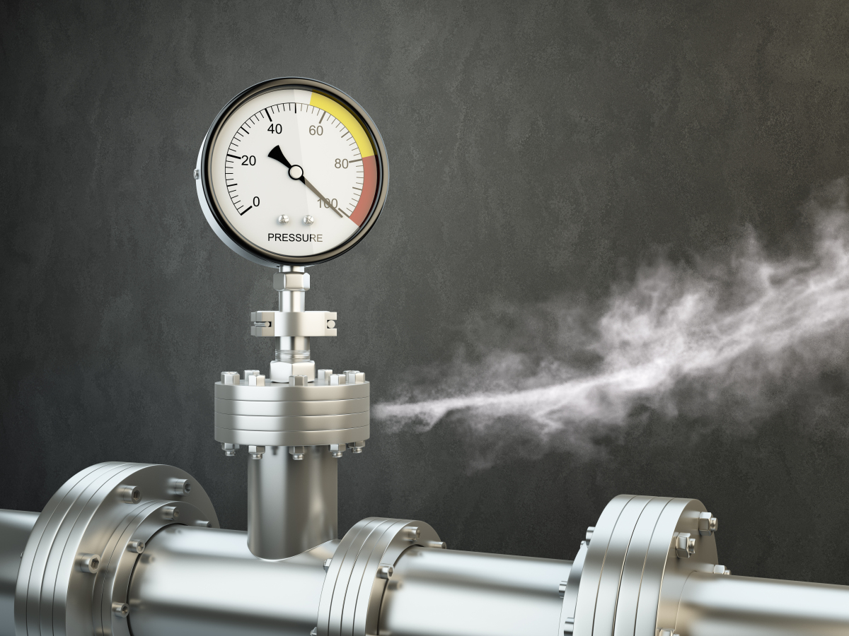
Pneumatic systems offer many advantages. Because the fluid can be air, leaks do not contaminate nearby surfaces as would be the case with hydraulic fluid, such as oil. Air is readily available so this makes pneumatic systems more portable. Because air can be moved through transmission lines very quickly, pneumatic systems can react more quickly than hydraulic systems in many applications.
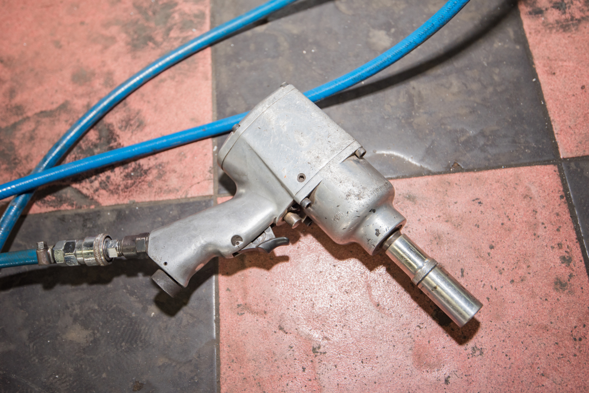
Applications of Pneumatic Systems
Pneumatic systems typically have a wider variety of actuators than do hydraulic systems. Especially if the pneumatic system uses air as its fluid, the compressed air can be returned to the surroundings by an actuator, simplifying the design of the system and opening up many new design possibilities. The following examples list some (but not nearly all) common applications of pneumatic systems.


Viscosity
The particles that make up a fluid experience forces of attraction toward each other. These attractive forces are responsible for keeping a raindrop together as it falls through the air, but they are also responsible for a key property of a fluid known as viscosity. Simply put, viscosity is a measure of how difficult it is to get a fluid to flow; the attractive forces between the particles make it difficult for the fluid to flow.

Laminar and Turbulent Flow

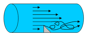
If there is an irregularity in the surface in contact with the fluid in motion, its particles will interact with the irregularity and this will disrupt their otherwise smooth and straight-line motion, resulting in chaotic paths for the particles known as eddies. An irregularity can be a physical barrier that is in the way, an opening that the fluid passes by, or even just a patch of pipe surface that is rougher than the rest of the pipe.
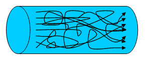
If you’ve ever flown through turbulence in an airplane, the chaotic motion of the air particles is obvious, as the air currents jostle the airplane on all sides and affect the lift of the wings and the ability of the pilot to control the flight. Fluids with low viscosity are more susceptible to turbulent flow than fluids with high viscosity. This makes sense, as the particles in a fluid with high viscosity are more strongly attracted to each other, so they might be less disturbed by an irregularity in a surface they are in contact with and recover from any chaotic motion induced by the irregularity more quickly, returning to a smooth and laminar flow.
 Canadian Contributions
John F. Allen was a physicist who was born in Winnipeg, Manitoba in 1908. In 1937, he co-discovered an unusual phase of matter known as a superfluid. A superfluid is a special type of fluid with zero viscosity. Having zero viscosity gives superfluids some interesting properties, and since susceptibility to turbulent flow increases with decreasing viscosity, a superfluid will be very susceptible to turbulent flow. In fact, a disturbance in a superfluid, such as a vortex caused by stirring part of it in a container, will continue to exist long after the stimulus is removed. Superfluid helium can appear to defy gravity as it climbs the walls of its container and spills over the rim. Allen completed his education in Canada but worked most of his career in the United Kingdom. He passed away in 2001 at the age of 92.
Applications of Laminar and Turbulent Flow
Turbulent flow wastes energy, as some energy is converted into kinetic energy of the fluid particles in eddies. As a result, engineers seek to reduce or eliminate turbulent flow wherever they can. In general, the closer a system can get to a laminar flow, with few or no eddies, the more efficient it will be.
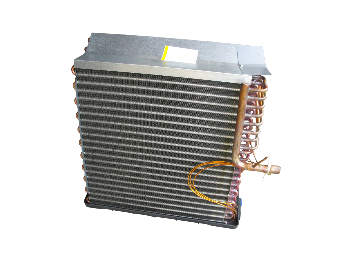
Despite laminar flow being desirable in many situations, turbulent flow also has its uses. For example, when constructing a heating or cooling coil, turbulent flow within the coil will result is more efficient heat transfer, as there will be more mixing of the fluid in the coil due to all of the eddies. If the flow in the coil were laminar, it would be difficult for heat to transfer to or from fluid in the middle of the tube making up the coil, so turbulence in this case can improve efficiency.
Bernoulli’s Principle
Daniel Bernoulli was a Swiss scientist who studied fluids in motion. He came to the conclusion that if a fluid is moving slowly, the pressure will be high and if a fluid is moving quickly, the pressure will be low. The speed Bernoulli referred to was the speed of the particles of the fluid (not the volumetric flow rate). A Venturi tube provides a good demonstration of this effect.
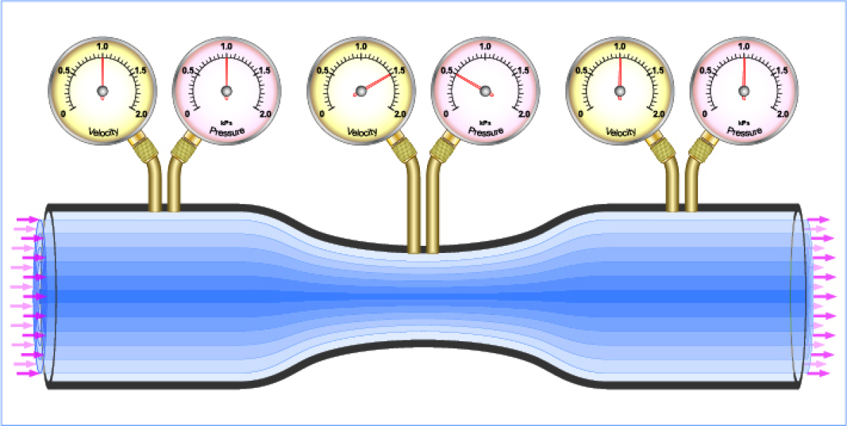
Bernoulli’s principle, as it applies to a Venturi tube, at first seems counterintuitive. All of those particles of fluid are being squished into a smaller diameter section of tube, so the pressure there must be higher, right? Wrong. The correct way to think about the fluid dynamics at work in a Venturi tube is to think about the energy in the fluid. Recall that pressure is a kind of potential energy in a fluid. The fluid in the Venturi tube is moving, so it also possesses kinetic energy. The fluid must speed up to travel through the smaller diameter tube, meaning the particles in that section of tube will have higher kinetic energy than the slower moving particles in the larger diameter sections of tube. Since energy is always conserved in a closed system, some of the potential energy resulting from the pressure the fluid is under is transformed into greater kinetic energy. So, when a fluid speeds up, the pressure goes down.
Another way to think about the Venturi tube is by imagining a particle of fluid as it transitions from the larger diameter section of tube to the smaller diameter section of tube. There must be some force acting on the particle to speed it up. There is, it is the pressure differential between the high pressure fluid in the larger diameter section and the low pressure fluid in the smaller diameter section that gives the particles a “push” to speed up . When they reach the transition from back to the final larger diameter section, there is again a pressure differential, but this time it is the higher pressure in the final larger diameter section of tube that acts to slow the particles down as they exit the smaller diameter section.
 Applications of Bernoulli’s Principle
For this learning task, you will analyze how Bernoulli’s Principle is used in a real-world application. Bernoulli’s Principle is used in many applications, including:
- Paint sprayer
- Gas engine carburetor
- Airplane wing
- Airspeed sensor (also known as a pitot tube)
- A baseball, soccerball, or other ball that spins while in flight
- Frisbee
- Bottle of perfume
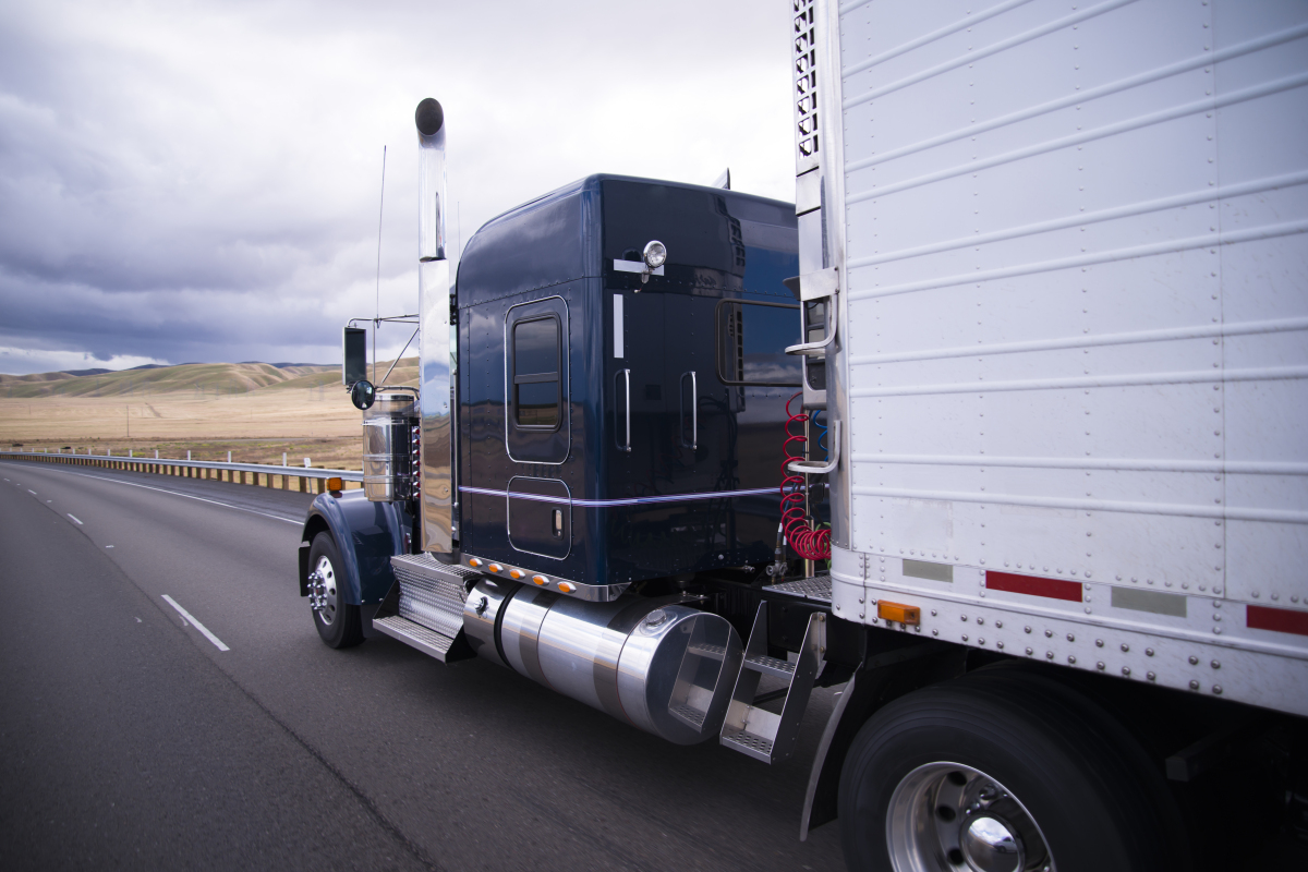
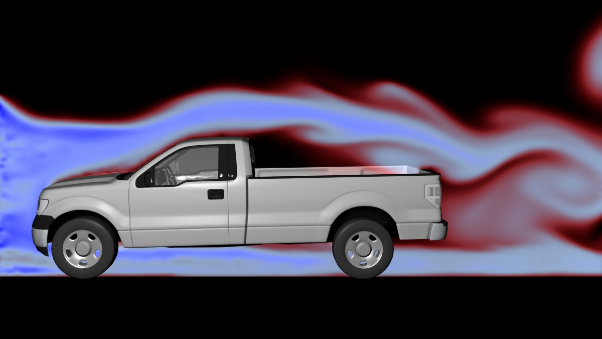
- Trucks driving side-by-side
- Race car spoiler
- Bunsen burner
- Other application as approved by your teacher
Select a real-world application of Bernoulli’s Principle to work with. Describe the device, how it operates and how Bernoulli’s Principle applies to it.
CONSOLIDATION
Summary
| Hydraulic Systems | Pneumatic Systems |
|---|---|
| Use an incompressible liquid |
Use a compressible gas |
|
Environmental risk from potential hydraulic fluid leaks |
Safety risks from potential energy stored in compressed gas |
|
Expensive to build but cheap to operate |
Cheap to build but expensive to operate, e.g., due to the need to run compressors to compensate for leaks |
|
Best used where large forces or exact positioning is required |
Best used where fast movement is required or contamination from hydraulic fluid is a concern |
|
Both use a variety of components including cylinders, pumps/compressors, transmission lines, fittings, valves and filters. |
|
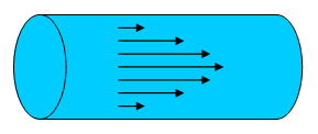
Laminar flow happens with higher viscosity fluids that are moving more slowly. The flow is orderly and efficient.
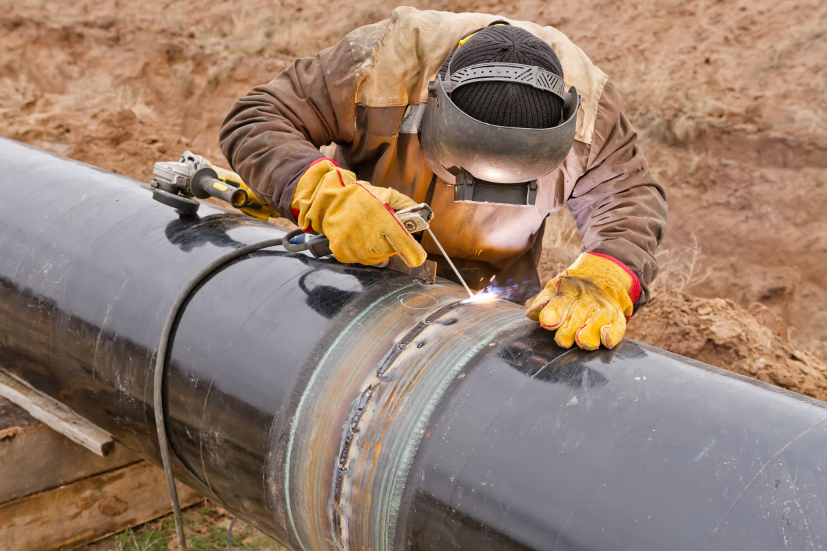
Turbulent flow happens with lower viscosity fluids that are moving more quickly. The flow is disorderly and some energy is transformed into kinetic energy of eddies, resulting in lower efficiency, e.g., in pipelines.
Bernoulli’s principle states that if a fluid is moving slowly, the pressure will be high and if a fluid is moving quickly, the pressure will be low.