Electricity and Magnetism
Kirchoff's Laws and Circuit Analysis
MINDS ON
Electric circuits are all around us. From the lights in our homes to the smartphones in our pockets, these circuits all follow very basic rules which we will explore in this activity.

 Reflection
Create a reflection to answer the following questions:
- Think about a route from your home to a destination, such as school or work. How many intersections do you pass through along the way? How many are 3-way intersections? 4-way? 5- or 6-way?
- If a car or pedestrian enters an intersection, are they able to stay or must they eventually move along?
- Think about a shopping mall with several levels, from bottom to top: parking garage, first floor, second floor, third floor. A person starts out waiting for an elevator on the first floor and takes it all the way to the third floor. They walk a bit on the third floor before taking the stairs down to the second floor. On the second floor they find an escalator to take down to the first floor, where they return to the elevator doors. How has the height of the person above the parking garage changed between the start of their journey and the end?
ACTION
Kirchhoff’s Current Law

The diagram depicts a node between three components in a circuit, with  flowing into the node, and
  and
and  flowing out of the node. An equation can be written using KCL to relate these three quantities, by arranging all current flows into the node on one side of the equal sign and all current flows out of the node on the other side of the equal sign:

If any two of the three currents at the node are known, the third can be easily calculated thanks to KCL.
Note: When more than three components are connected, the node is considered to include all points of connection between them. The following diagram illustrates how to create an equation for a node with more than three connected components:
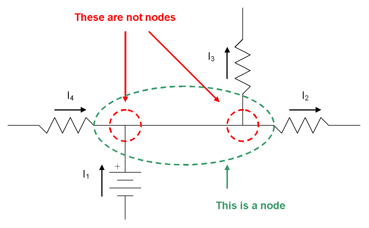
The KCL equation for the node in the diagram is:
Recall that a node is a connection between components in a circuit. The two connection points circled in red in the diagram are not nodes because there is no component between them. The node is the connection between all four components in the diagram.
Parallel Circuits
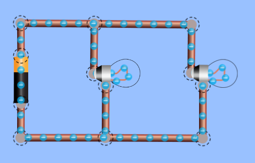
Kirchhoff’s Current Law allows us to analyze parallel circuits quantitatively. A parallel circuit is one in which there is more than one path for current to flow through. A basic parallel circuit can be constructed from one power source, e.g., a battery, and two or more loads, e.g., light bulbs.

Parallel circuits like this have the following properties:
- The sum of the current flows through each load is equal to the current flow through the source. This is a direct result of KCL.
- The voltage drops across all of the components in the circuit are equal. For now, this statement will have to be accepted as fact; we will develop a rationale for it later in this activity.
- As more light bulbs are added to the circuit, the brightness of the other light bulbs is not affected.
- If a light bulb burns out, the other light bulbs are not affected.
 Example
Calculate the current flow through the battery in the circuit shown in the diagram.

Given:


Required:
We are being asked to calculate the current flow through the battery,  .
.

Analyze:
We begin by drawing arrows to represent the current flow through each component in the circuit and labelling the nodes using lowercase letters.

We can create KCL equations for each node:
For node a: 

For node b: 

We can also create Ohm’s law equations for each resistor:
For resistor 1: 

For resistor 2: 

Recall that for now we are accepting as fact the idea that the voltage drops across all components in a parallel circuit are equal. This means:


We will choose to work with the KCL equation for node a as well as the Ohm’s law equations to solve this problem.
Solve:
First, we will calculate the current flow through each resistor using the Ohm’s law equations:


Next, using the KCL equation for node a:


Paraphrase:
The current flowing through the battery is 1.1 A.
Note: In the process of solving for the current flow through the battery, we have completely analyzed the circuit, solving for all unknown voltages and current flows.
 Linear Independence of KCL Equations
In the example, the equations for nodes a and b are actually the same equation in different forms. A full discussion of this result is beyond the scope of our course, but, the main idea to remember is that if you have a circuit with n nodes, you will only be able to create (n – 1) independent equations for it based on KCL. That is to say, any one of your node equations will be a linear combination of the other equations. This means that when we apply KCL to analyze circuits, we can exclude one of the node equations from the analysis. Since any node equation is a linear combination of the other equations, we can choose which one to exclude.
Both node equations in the example were exactly the same except that the terms were on opposite sides, so it didn’t matter too much which equation was excluded. If you have a more complex circuit with equations that are not obvious combinations of each other, it would make sense to exclude one of the more complex equations and keep all of the simpler ones to make your analysis easier.
Parallel Equivalent Resistance
Resistors in parallel can be replaced with a single parallel equivalent resistance.
The relation between the resistances of individual resistors in a parallel circuit, R1, R2, R3, etc. and the parallel equivalent resistance, RP, can be expressed mathematically by the following equation:
Solving for the parallel equivalent resistance of the previous example, with  and
and  :
:
The next step is a little tricky – remembering that we can create a fraction with the same value as any number by making the numerator equal to the number and the denominator equal to 1, we then “flip” both sides of the equation to solve for  .
.
The parallel equivalent resistance of the resistor network in the previous example is  . We will now analyze the current flow through the battery in a circuit with the same supply voltage, 15 V and a single resistor with
  :
:

First, we’ll add current flow arrows and node labels to the diagram:

Next, we’ll create KCL equations for all nodes.
For node a: 
For node b: 
Now, we create an Ohm’s law equation for the resistor:
For resistor  :
: 
Recalling that the voltage drops across all components in a parallel circuit are equal:


We can now solve for the current flowing through the parallel equivalent resistor:


Finally, using the KCL equation for node a we have:

The parallel equivalent resistance of  has resulted in a current flow through the battery of 1.1 A, exactly the same as the two resistors connected in parallel in the previous example.
A parallel equivalent resistance is the resistance that can replace a network of resistors connected in parallel and allow the rest of the circuit to operate with the same characteristics (in this case, current flow through the battery).
This concept of a parallel equivalent resistance has a few applications:
- If a needed resistor is not available, it might be possible to construct a network with the necessary parallel equivalent resistance. For example, if you needed a
 resistor, but had only
  resistors on hand, you could create a parallel resistor network with two
  resistors that would have a parallel equivalent resistance of
  , and use this where you needed a
  resistor.
 - If you are analyzing circuits, it can sometimes be faster to determine the parallel equivalent resistance of a network of resistors connected in parallel than to complete the same analysis using Kirchhoff’s laws directly.
 Constructing and Analyzing Parallel Circuits
For this learning task, you will use the PhET DC circuit construction kit to simulate some parallel circuits, as well as analyze parallel circuits using Kirchhoff’s Current Law and Ohm’s Law. Use the GRASP method to communicate your calculations and be sure to state your final answers using the correct number of significant digits.
Complete the following tasks:
- Create the following circuit using the simulator. Use an ammeter to measure and record the current flow through the battery and each light bulb. Use a voltmeter to measure and record voltage across the battery and each light bulb.
by PHET - University of Colorado - Complete a calculation to verify KCL for 1 node in the circuit.
- Predict the current flow through the battery if a 3rd light bulb were added to the circuit. Explain your prediction using KCL.
- Add a 3rd light bulb to the circuit. Measure and record the current flow through the battery. Did your prediction match the result?
- Create a schematic diagram of a circuit that has a battery supplying 23 V to three resistors (
 ,
,  and
and  ) connected in parallel.
 - Complete an analysis, using KCL and Ohm’s Law, to predict all V and I in the circuit.
- Create the circuit from the schematic diagram you created in question 5. Measure and record all V and I and compare to your calculated values.
- Complete a calculation to determine the equivalent parallel resistance that could replace the resistors in the schematic diagram you created in question 5.
Kirchhoff’s Voltage Law

The diagram depicts a loop with three components in a circuit, with nodes a, b and c. KVL tells us that the voltage increase from node a to b must be equal to the sum of the voltage drops from node b to c and from node c to a. An equation can be written using KVL to relate these three quantities. If any two of the three potential differences in the loop are known, the third can be easily calculated thanks to KVL.
KVL requires a little more thought to write equations than KCL, where the direction of the current flow arrows clearly indicated the side of the equation in which they should appear. To create a KVL equation for a loop in a circuit, follow these steps:
- Draw arrows to represent the current flow through each component in the loop. You can try to keep the arrows in the direction that current will actually flow, but you do not have to. If you get the direction wrong for a current flow arrow, any analysis you do will result in a negative value for the current flow through that component and the potential difference across it, which will tell you that the current is flowing opposite the arrow you drew in this step and the potential difference has polarity opposite to the convention established in step 4.
- Pick a node in the loop as a starting point.
- Pick a direction to begin creating the equation for the loop.
- Progress around the loop and create terms for your KVL equation as you go:
- For power sources such as batteries, the terms will be positive if your progression emerges from the positive terminal and negative otherwise. This is because power sources add energy to electric current as it flows through.
- For loads such as resistors, the terms will be negative if your progression is in the same direction as the current flow arrow you drew in step 1 and positive otherwise. This is because loads absorb energy from electric current as it flows through.
- When your progression reaches the node that you started at, add an = 0 and you have created a KVL equation for that loop.
Example
Let’s create a KVL equation for this circuit:
The first step is to draw current flow arrows with all of the components:

The next step is to pick an arbitrary node as a starting point. Let’s pick node a.
The next step is to pick an arbitrary direction (clockwise or counter-clockwise) to progress through the loop to build-up the KVL equation. Let’s pick clockwise.
The next step is the most involved, as we progress around the loop adding terms to our KVL equation.
We progress through the battery to node b, which is connected to the positive terminal of the battery, so the first term in the KVL equation is:

The next component is a resistor, and we progress through it in the direction of the current flow arrow, so we add to the KVL equation, with a negative term:

The next component is also a resistor, and we also progress through it in the direction of the current flow arrow, so we add to the KVL equation again, also with negative term:
We have now arrived back at the starting point so we add = 0 to complete the KVL equation (and drop the plus sign on the first term to tidy it up a bit):

Let’s consider some other options, since we are afforded the choice of which way to draw the arrows, which node to start on and which direction to progress around the loop.
Let’s pick a different starting point, node b. Progressing around the loop still in a clockwise direction, we would find the KVL equation for the loop to be:
This is the same equation, with the order of the terms changed.
Let’s pick the same starting point, node a. Progressing around the loop in a counter-clockwise direction, we would find the KVL equation for the loop to be:
This is the same equation, with the order of the terms changed and each term multiplied by -1.
Let’s change the direction of one of the current flow arrows drawn on the original diagram,  :
:

If we again start at node a and progress clockwise, we will find the KVL equation for the loop to be:
This is a different equation, but, if we completed an analysis of this circuit using both our original equation and this different equation, the values that we found for  and
and  would be exactly equal but have the opposite sign. For example, we might use the original equation, complete the analysis and find that
  . If we use the different equation, and complete the analysis, we would find that
  . This is two different ways of finding the same real-world phenomenon, that
  of current is flowing from node b to node c.
Regardless of which direction you draw your current flow arrows, which node you select as a starting point and which direction you choose to progress around the loop, the results of your analysis will be the same. With that said, it probably makes sense to draw current flow arrows in the direction the current will flow, to keep the math as simple as possible.
Series Circuits

Kirchhoff’s Voltage Law allows us to analyze series circuits quantitatively. A series circuit is one in which there is only one path for current to flow through. A basic series circuit can be constructed from one power source, e.g., a battery, and two or more loads, e.g., light bulbs. Series circuits like this have the following properties:
- The current flowing through all of the components in the circuit is equal. This follows from KCL, since at each junction the sum of the current flowing in must equal the sum of the current flowing out. Each component in the series circuit has the same current flow as the components it is connected to, and since there is only one path for current to follow, this applies to all components in the circuit.
- The sum of the voltage drops across each load is equal to the voltage of the source. This is a direct result of KVL:
The KVL equation for this circuit is:
This can be re-arranged to the following form:

The sum of the voltage drops across each resistor is equal to the voltage of the power source.
- As more light bulbs are added to the circuit, the brightness of the other light bulbs decreases.
- If a light bulb burns out, the flow of current in the circuit is interrupted. This results in the other light bulbs going out, too.
Example
Calculate all unknown V and I for the circuit shown in the diagram.

Given:


Required:
We are being asked to calculate all unknown V and I.


Analyze:
We begin by drawing arrows to represent the current flow through each component in the circuit and labelling the nodes using lowercase letters.

We can create KCL equations for each node:
For node a: 
For node b: 
For node c: 
So, in a series circuit we have: 
We can also create a KVL equation for the circuit loop:

We can also create Ohm’s law equations for each resistor:
For resistor 1: 
For resistor 2: 
We will work with the KCL, KVL, and Ohm’s law equations to solve this problem.
Solve:
We will begin with the KVL equation and substitute in the Ohm’s law equations:


Recalling that  and substituting in known values:


We can now use the Ohm’s law equations to solve for  and
and  (again recalling that
  ).
).


Paraphrase:
The current flowing through the battery and each of the resistors is 0.27 A. The voltage drop across  is 6.0 V and the voltage drop across
  is 9.0 V.
Series Equivalent Resistance
Resistors in series can be replaced with a single series equivalent resistance. The relation between the resistances of individual resistors in a series circuit,  ,
,  ,
,  , etc. and the series equivalent resistance,
  , can be expressed mathematically by the following equation:

Solving for the series equivalent resistance of the previous example, with  and
and  :
:

The series equivalent resistance of the resistor network in the previous example is  . We’ll now analyze the current flow through the battery in a circuit with the same supply voltage,
  and a single resistor with
  :
:

First, we’ll add current flow arrows and node labels to the diagram:

Next, we’ll create KCL equations for all nodes:
For node a: 
For node b: 
Next, we’ll create a KVL equation for the loop:


Now, we create an Ohm’s law equation for the resistor:
For resistor  :
: 


The series equivalent resistance of  has resulted in a current flow through the battery of 0.27 A, exactly the same as the two resistors connected in series in the previous example.
A series equivalent resistance is the resistance that can replace a network of resistors connected in series and allow the rest of the circuit to operate with the same characteristics (in this case current flow through the battery).
This concept of a series equivalent resistance has the same applications as a parallel equivalent resistance:
- If a needed resistor is not available, it might be possible to construct a network with the necessary series equivalent resistance. For example, if you needed a
 resistor but had only
  resistors on hand, you could create a series resistor network with two
  resistors that would have a series equivalent resistance of
  , and use this where you needed a
  resistor.
 - If you are analyzing circuits, it can sometimes be faster to determine the series equivalent resistance of a network of resistors connected in series than to complete the same analysis using Kirchhoff’s laws directly.
Constructing and Analyzing Series Circuits
For this learning task, you will use the PhET DC circuit construction kit to simulate some series circuits as well as analyze series circuits using Kirchhoff’s laws and Ohm’s Law. Use the GRASP method to communicate your calculations and be sure to state your final answers using the correct number of significant digits.
Complete the following tasks:
- Create the following circuit using the simulator. Use an ammeter to measure and record the current flow through the battery and each light bulb. Use a voltmeter to measure and record voltage across the battery and each light bulb.
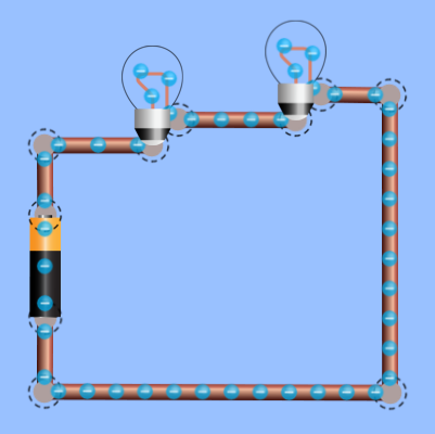
by PHET - University of Colorado - Complete a calculation to verify KVL for the circuit.
- Predict the current flow through the battery if a 3rd light bulb were added to the circuit. Explain your prediction using Kirchhoff’s Laws.
- Add a 3rd light bulb to the circuit. Measure and record the current flow through the battery. Did your prediction match the result?
- Create a schematic diagram of a circuit that has a battery supplying 23 V to three resistors (
 ,
,  and
and  ) connected in series.
 - Complete an analysis, using Kirchhoff’s laws and Ohm’s Law, to predict all V and I in the circuit.
- Create the circuit from the schematic diagram you created in question 5. Measure and record all V and I and compare to your calculated values.
- Complete a calculation to determine the equivalent series resistance that could replace the resistors in the schematic diagram you created in question 5.
Revisiting Parallel Circuits
A statement was made in the parallel circuit portion of this lesson that the voltage drops across all of the components in a parallel circuit are equal. This statement was not supported by any analysis until now.
Consider the following parallel circuit:
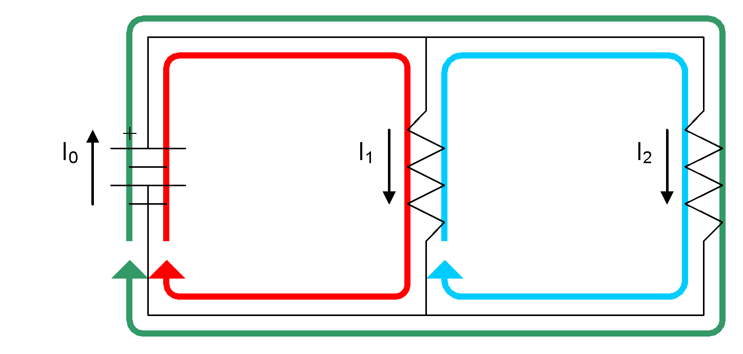
There are three possible loops in the circuit. The KVL equations for these loops are as follows:
For the red loop: 
For the blue loop: 
For the green loop: 
These equations can easily be re-arranged to show that for the red loop,  , for the blue loop,
  and for the green loop, it should not be a surprise to find that
  . Applying KVL to a parallel circuit leads to the rule that the potential differences in a parallel circuit are all equal.
CONSOLIDATION
Summary:
Kirchhoff’s Current Law states that the sum of the currents flowing into a node in a circuit must equal the sum of the currents flowing out of the node.
A circuit of light bulbs connected in parallel has the following characteristics:
- The sum of the current flows through each load is equal to the current flow through the source.
- The voltage drops across all of the components in the circuit are equal.
- As more light bulbs are added to the circuit, the brightness of the other light bulbs is not affected.
- If a light bulb burns out, the other light bulbs are not affected.
A network of resistors connected in parallel may be replaced by a single parallel equivalent resistance, or vice-versa.

Kirchhoff’s Voltage Law (KVL) states that for any closed loop in a circuit, the sum of the potential differences across all components is zero.
A circuit of light bulbs connected in series has the following characteristics:
- The current flowing through all of the components in the circuit is equal.
- The sum of the voltage drops across each load is equal to the voltage of the source.
- As more light bulbs are added to the circuit, the brightness of the other light bulbs decreases.
- If a light bulb burns out, the other light bulbs go out too.
A network of resistors connected in series may be replaced by a single series equivalent resistance, or vice-versa.
