Electricity and Magnetism
Analyzing Mixed Circuits
MINDS ON
Electrical technology is used in many different ways, from household devices such as vacuum cleaners and televisions to industrial uses such as elevators, lift trucks, and conveyor belts. This technology has revolutionized the world in which we live.
 Reflection
Create a reflection to answer the following questions:
- List the number of devices you use in a typical day that use electrical technology in some way.
- For as many devices as possible, write down an alternative device that could be used that does not use electrical technology. For example, instead of flipping a switch to turn on a ceiling mounted electric light, you might have to fill a lamp with oil and find a match to light it.
- Reflect on any changes to your daily routine that would be required if you were required to switch to the alternative devices you identified.
ACTION
Analyzing Mixed Circuits
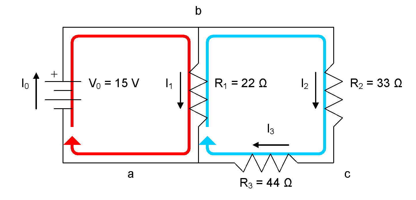
Some circuits contain a mixture of parallel and series components. An example is shown in the following diagram:

When analyzing a mixed circuit, one approach you can take is to apply the parallel and series equivalent resistance techniques to simplify the circuit down to an equivalent resistance.
 Example
Calculate the current flow through the battery for the mixed circuit shown in the diagram.
Given:


Required:
We are required to find the current flow through the battery,  .
.

Analyze:
We will first find an equivalent series resistance for  and
and  :
:

Note that  is not included in this calculation, as only
  and
and  are in series with each other. Using this equivalent series resistance, the circuit analysis task is simplified:

But we’re not done, yet!  and
and  are connected in parallel, so we can calculate a parallel equivalent resistance to replace them with and simplify the circuit further:
Note that in our previous circuit simplification step,  and
and  were in parallel with each other, so it is these values that we use to calculate a parallel equivalent resistance, not
  and
and  from the original circuit. The circuit has now simplified to:

Knowing that in this circuit,  and
and  , we can find the current flow through the battery:
Solve:

Paraphrase:
The current flow through the parallel equivalent resistance is 0.88 A, so the current flow through the battery is 0.88 A.
If the question asked us to solve for all unknown V and I, we could then work backwards, using the in-between simplified circuit diagram:
We know, that in a parallel circuit, the voltage drops are equal among components, so this tells us that:

We can then complete an Ohm’s Law calculation to find the current through  :
:


Similarly,  can be calculated as follows:


Next, we revisit to the original circuit diagram and analyze the branch containing  and
and  .
.
The trick here is to know that the current we calculated for  in the last step is the current flowing through that branch, and also the current flowing through
  and
and  . So, we know:

The last step remaining is to calculate  and
and  using Ohm’s Law. For
  :
:


Similarly,  can be calculated as follows:


We have now solved for all unknown V and I in the circuit.
A final check of our arithmetic using KVL for the loop comprised of the battery,  and
and  gives:

0=0
Our arithmetic checks out okay!

Applying Kirchhoff’s Laws Directly
You can also apply Kirchhoff’s Laws, along with Ohm’s Law, to solve for all unknown V and I in a circuit. To do this, you will need to generate KCL, KVL, and Ohm’s Law equations, select equations that are linearly independent, and solve the system of equations you selected.
Recall that for KCL equations, if you have n nodes in a circuit, you can only create (n – 1) linearly independent equations.
When creating KVL equations, you have a lot of options. A good rule of thumb is to create KVL equations only for loops that do not enclose other loops (known as “meshes”). These will all be linearly independent. If you have d total devices in the circuit, creating mesh equations will give you (d – (n – 1)) equations.
When creating Ohm’s Law equations in a mixed circuit analysis, these are all linearly independent.
To apply this technique to the previous example mixed circuit, we first note that the circuit has 3 nodes and 2 meshes. We should be able to generate 2 linearly independent KCL equations and 2 linearly independent KVL equations. Ohm’s law will provide 3 more linearly independent equations and the simplest equation of all,  , provides one more. We will wind up with 8 equations and 8 V and I, and we can solve for all of these with a little algebra. Of course, one of those 8 is already solved for us (
 ) so this gets us off to a good start.
First, let’s develop the KCL equations for this circuit. We begin by drawing arrows to represent the current flow through each component in the circuit and labelling the nodes using lowercase letters:

For node a: 
For node b: 
For node c: 
We need to select one of the equations to exclude. We’d like to keep the equation for node c because it is simple, and we’ll arbitrarily decide to keep the equation for node b, as well. The equation for node a is excluded.
Next, we will develop KVL equations for each mesh in the circuit. Remember, meshes are loops that do not enclose any other loops.
For the red mesh: 
For the blue mesh: 
Next, the Ohm’s Law equations:


Finally, remember the simplest of all equations:

This makes 8 equations with 8 V and I (one of the equations tells us directly that  ). The only remaining task is to solve the other 7 equations. The 8 equations we will use are:

|

|

|
|

|
|
|
|


At this point, it is a bit of a puzzle to look at your equations and see what you know that you can substitute and solve easily. The red mesh KVL equation seems promising:


Next, we apply Ohm’s Law to find  :
:


At this point, there aren’t too many promising equations, but the blue mesh KVL equation will work, with a little substitution of Ohm’s Law equations now that we know  .
.


Remember that one of our equations tells us that  .
.


Now, we can solve for  using Ohm’s Law:


Now, solving for  and
and  :
:


Finally, solving for the current flow through the battery:


The values for all V and I in the circuit match exactly with the parallel and series equivalent reduction method. The choice is yours whether you prefer to reduce the circuit complexity using parallel and series resistances, or generate and solve a system of equations. Either method will find all V and I in a mixed circuit.
 Analyzing Mixed Circuits
For this learning task, you will analyze a mixed circuit using Kirchhoff’s laws and Ohm’s Law. Use the GRASP method to communicate your calculations and be sure to state your final answers using the correct number of significant digits.
Complete the following tasks:
- Complete an analysis, using KCL, KVL, and Ohm’s Law, to predict all V and I in the following circuit.

- Use the simulator to construct the circuit from the schematic diagram in question 1. Measure and record all V and I and compare to your calculated values from question 1.
 Careers

An electrician is responsible for installing and maintaining electrical wiring and equipment in residential, commercial, and industrial settings. Electricians may be employed by, e.g., a manufacturing company to maintain their electrical systems, or they may be self-employed. Since electricians work with circuits that may have dangerously high voltage and/or current characteristics, safety is the top priority. Electricians generally work a typical 40 hour work week, with day shifts from Monday to Friday. Electricians working during the peak of construction season or in an industrial plant may deviate from this predictable schedule.
Electricians in Ontario are required to complete classroom studies and an apprenticeship before they can become certified in their trade. Find out more about a career as an electrician.
 Evolution of Electrical Technology
Electrical technologies are continuously evolving to provide greater safety and efficiency, as well as lower environmental impacts.
You should:
- Conduct research about a specific electrical technology.
- Provide a description of the electrical technology.
- Provide specific examples of impacts the evolution of the electrical technology has had on people and/or the environment.
- Indicate whether each impact is positive or negative and explain your reasoning.
 Canadian Contributions

CONSOLIDATION
Summary:
When analyzing mixed circuits, Kirchhoff’s Laws and Ohm’s Law apply just as they do in parallel and series circuits.
One method to use when analyzing a mixed circuit is to reduce the circuit to a single equivalent resistance, solve for any unknown V or I in the equivalent resistance circuit, and then work backwards to solve for all unknown V and I in the original circuit.
Another method that can be used to analyze a mixed circuit is to use Kirchhoff’s Laws and Ohm’s Law to create a system of equations, which can then be solved to find all unknown V and I in the circuit.
When selecting equations to create a system of equations to solve for all unknown V and I, you will need twice the number of linearly independent equations as the circuit has devices.
- Each device will have a linearly independent equation, e.g., V0 = 12 V or V1 = I1R1.
- KCL will provide (n - 1) additional linearly independent equations where n is the number of nodes in the circuit.
- KVL will provide all remaining linearly independent equations. A good process to ensure that the KVL equations are linearly independent is to create a KVL equation for each mesh in the circuit.
Both methods of analyzing a mixed circuit will produce the same results.